
Circuit Documentation
Summary of the Circuit
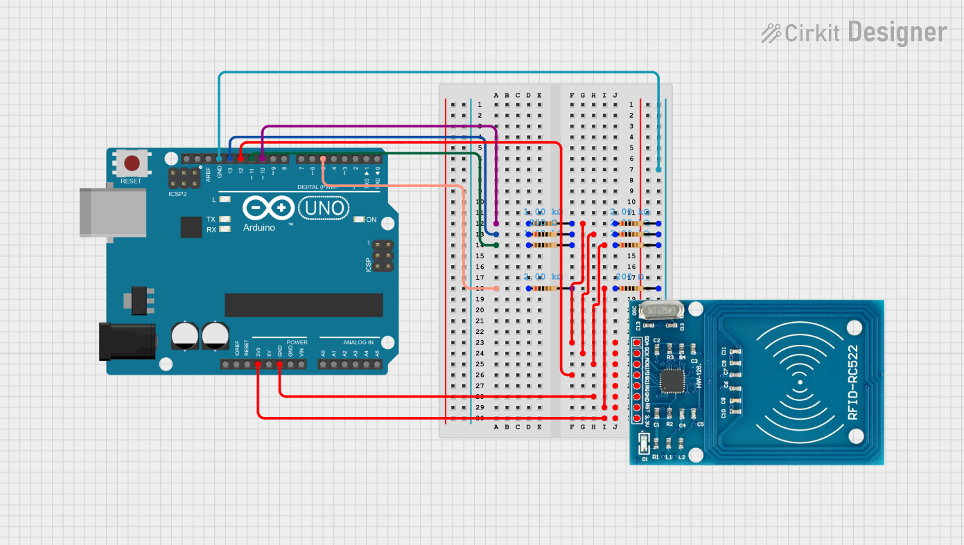
This circuit integrates an Arduino UNO microcontroller with an RFID-RC522 reader and multiple resistors. The purpose of the circuit is not explicitly stated, but it can be inferred that the RFID-RC522 is used for RFID communication, and the resistors are likely used for signal conditioning or pull-up/pull-down purposes. The Arduino UNO is the central processing unit that controls the RFID reader and processes the data.
Component List
Arduino UNO
- Microcontroller board based on the ATmega328P
- It has 14 digital input/output pins, 6 analog inputs, a 16 MHz quartz crystal, a USB connection, a power jack, an ICSP header, and a reset button.
Resistors
- Passive two-terminal electrical components used to implement electrical resistance as a circuit element.
- In this circuit, resistors with different resistance values are used, specifically 200 Ohms, 1000 Ohms, and 2000 Ohms.
RFID-RC522
- An RFID module that operates at 13.56 MHz.
- It is commonly used for RFID communication and is capable of reading and writing to various RFID tags.
Wiring Details
Arduino UNO
- Digital Pin D10: Connected to a 1000 Ohm resistor.
- Digital Pin D13: Connected to a 200 Ohm resistor.
- Digital Pin D11: Connected to a 1000 Ohm resistor.
- Digital Pin D5: Connected to a 2000 Ohm resistor.
- Digital Pin D12: Connected to the MISO pin of the RFID-RC522.
- 3.3V Pin: Supplies power to the VCC (3.3V) pin of the RFID-RC522.
- GND Pins: Connected to the GND pin of the RFID-RC522 and the second pins of all resistors.
Resistors
- 200 Ohm Resistor: One end connected to Arduino UNO's Digital Pin D13, the other end to the ground.
- 1000 Ohm Resistors: Each one has one end connected to an Arduino UNO digital pin (D10 or D11) and the other end to the ground.
- 2000 Ohm Resistors: Each one has one end connected to an Arduino UNO digital pin (D5) or the RST pin of the RFID-RC522, and the other end to the ground.
RFID-RC522
- SDA: Connected to a 2000 Ohm resistor.
- SCK: Connected to a 2000 Ohm resistor.
- MOSI: Connected to a 2000 Ohm resistor.
- MISO: Connected to Arduino UNO's Digital Pin D12.
- IRQ: Not connected.
- GND: Connected to Arduino UNO's GND pin.
- RST: Connected to a 2000 Ohm resistor.
- VCC (3.3V): Powered by Arduino UNO's 3.3V pin.
Documented Code
Arduino UNO Code (sketch.ino)
void setup() {
  // put your setup code here, to run once:

}

void loop() {
  // put your main code here, to run repeatedly:

}
The provided code is a template with empty setup() and loop() functions, which are the standard structure for Arduino sketches. The setup() function is intended to contain initialization code that runs once when the microcontroller is powered on or reset. The loop() function is for code that runs continuously as long as the Arduino is powered.
Additional Files
- documentation.txt: No code provided. This file is presumably intended for additional documentation or notes related to the code.