
Solar-Powered Environmental Monitoring Station with GSM Reporting
View and Edit Project In Cirkit Designer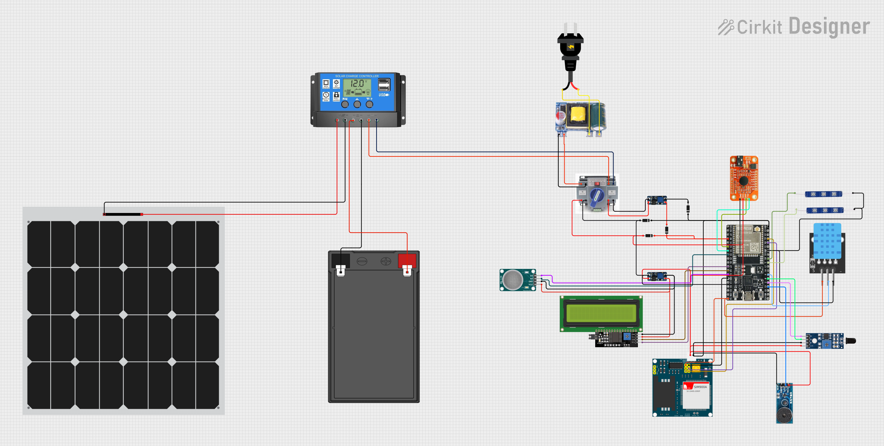
Circuit Documentation
Summary
The circuit in question appears to be a solar-powered system with a backup AC power source. It includes a solar panel connected to a charge controller, which in turn charges a 12V battery. The system can switch between solar and AC power using an Automatic Transfer Switch (ATS). The circuit also includes a DC-DC boost converter, various sensors, a GSM module (SIM900A), an ESP32 microcontroller, LEDs, a buzzer, an LCD display, and a voice recognition module. The circuit is designed to monitor environmental parameters and provide visual and auditory feedback.
Component List
Solar Panel
A photovoltaic panel that converts sunlight into electrical energy, providing a renewable power source for the circuit.
12V 7Ah Battery
A rechargeable battery that stores electrical energy for use when the solar panel is not generating sufficient power.
Solar Charge Controller
A device that regulates the voltage and current coming from the solar panels going to the battery to prevent overcharging and prolong the battery's life.
ATS (Automatic Transfer Switch)
A switch that automatically transfers power sources between the solar panel system and the AC power source.
AC Source
An alternative power source that provides AC voltage, used when solar power is insufficient.
DC-DC Boost Converter
A power converter that steps up the voltage from a lower voltage to a higher voltage, used to power various components in the circuit.
SIM900A
A GSM/GPRS module that allows the circuit to communicate with the GSM network for sending SMS, making calls, etc.
Diodes
Semiconductor devices that allow current to flow in one direction only, used for protecting the circuit from reverse current.
ESP32-WROOM-32UE
A powerful microcontroller with Wi-Fi and Bluetooth capabilities, used for controlling and monitoring various functions of the circuit.
MQ-136 Hydrogen Sulfide Gas Sensor
A sensor that detects the presence of hydrogen sulfide gas in the environment.
TEMP Sensor
A temperature sensor that measures the ambient temperature.
LCD Display 16x4 I2C
An alphanumeric display that shows information to the user, such as sensor readings or system status.
Sensor SHT113 Flame
A flame sensor that detects the presence of fire or flame in the environment.
12V Blue LEDs
Light-emitting diodes that provide visual indication or status.
Buzzer Module
An audio signaling device that emits a tone as an alert or indication.
Voice Recognition Module
A module that can recognize spoken commands and convert them into electronic signals for control purposes.
Mini AC-DC 110V-230V to 5V 700mA Module
A power supply module that converts AC voltage to 5V DC, used to power the circuit components.
Wiring Details
Solar Panel
+connected to Solar Charge ControllerSolar Cell +-connected to Solar Charge ControllerSolar Cell -
12V 7Ah Battery
12v +connected to Solar Charge ControllerBattery +12v -connected to Solar Charge ControllerBattery -
Solar Charge Controller
Solar Cell +andSolar Cell -connected to Solar PanelBattery +andBattery -connected to 12V 7Ah BatteryLoad +andLoad -connected to ATS
ATS
+connected to Solar Charge ControllerLoad +, Mini AC-DC Module5v, and various+inputs on other components-connected to Solar Charge ControllerLoad -, Mini AC-DC ModuleGND, and various-inputs on other components
AC Source
+connected to Mini AC-DC ModuleLife-connected to Mini AC-DC ModuleNeutral
DC-DC Boost Converter
VIN+andVIN-connected to ATSVOUT+andVOUT-connected to various components requiring boosted voltage
SIM900A
GNDconnected to ESP32GND5Vconnected to ESP325V5VTconnected to ESP32TX5VRconnected to ESP32RX
Diodes
- Anodes connected to various positive voltage outputs
- Cathodes connected to various negative voltage inputs or ground
ESP32-WROOM-32UE
- Various GPIO pins connected to sensors, LEDs, LCD display, and communication modules
3v3,EN,GND, and5Vconnected to power sources and ground as required
MQ-136 Hydrogen Sulfide Gas Sensor
VCCandGNDconnected to DC-DC Boost Converter outputsA0andD0connected to ESP32 GPIO pins
TEMP Sensor
5VandGNDconnected to ESP325VandGNDD3connected to ESP32 GPIO pin
LCD Display 16x4 I2C
SCLandSDAconnected to ESP32 I2C pinsVCCandGNDconnected to DC-DC Boost Converter outputs
Sensor SHT113 Flame
VCCandGNDconnected to ATS+and-A0andD0connected to ESP32 GPIO pins
12V Blue LEDs
VCCconnected to ESP32 GPIO pinsGNDconnected to ESP32GND
Buzzer Module
Vccconnected to ATS+GNDconnected to ESP32GNDI/Oconnected to ESP32 GPIO pin
Voice Recognition Module
VCCandGNDconnected to ATS+and-RDXandRTXconnected to ESP32 GPIO pins
Mini AC-DC 110V-230V to 5V 700mA Module
5vandGNDconnected to ATS+and-NeutralandLifeconnected to AC Source-and+
Documented Code
No code was provided in the input. If code is available for the microcontrollers or other programmable components in the circuit, it should be documented here with explanations for each function and routine. The code would typically include initialization routines, main loops, interrupt service routines, and utility functions, along with comments explaining the purpose and functionality of each section.