
Circuit Documentation
Summary
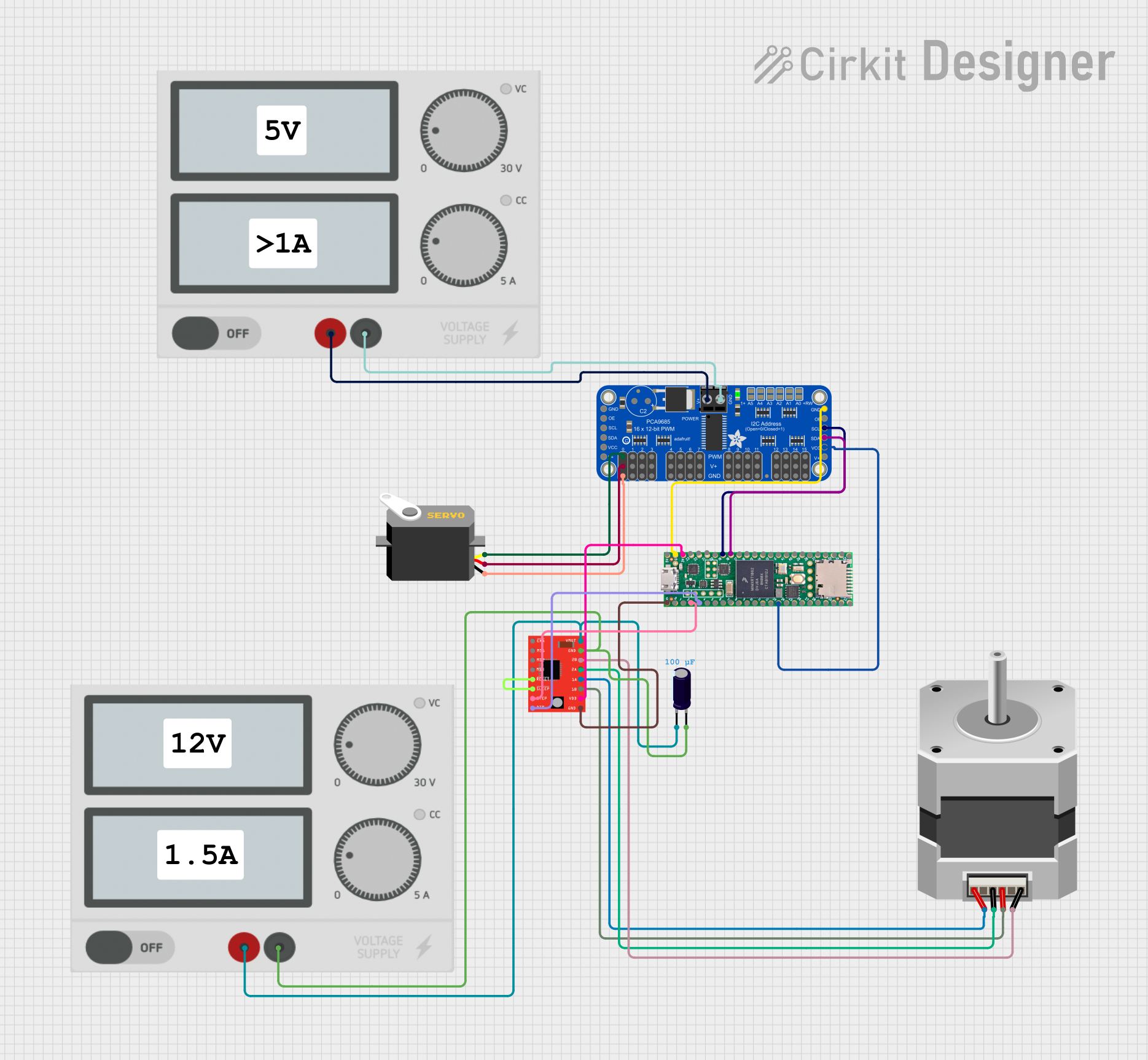
This circuit is designed to control a bipolar stepper motor using an A4988 Stepper Motor Driver, which is interfaced with a Teensy 4.1 microcontroller. Additionally, the circuit includes an Adafruit PCA9685 PWM Servo Breakout to control a servo motor. Power is supplied to the circuit through two separate power supplies, one for the stepper motor driver and one for the PWM servo breakout. An electrolytic capacitor is used to stabilize the voltage supply to the stepper motor driver. The circuit does not include any embedded code for the microcontroller.
Component List
A4988 Stepper Motor Driver (Red)
- Description: A module to drive a bipolar stepper motor.
- Pins: ENABLE, MS1, MS2, MS3, RESET, SLEEP, STEP, DIR, VMOT, GND, 2B, 2A, 1A, 1B, VDD
Teensy 4.1
- Description: A high-performance microcontroller board.
- Pins: Ground, 0-33, 3v, 5V/Input, 3V, 23-41
Adafruit PCA9685 PWM Servo Breakout
- Description: A 16-channel, 12-bit PWM Fm+ I2C-bus LED controller.
- Pins: 5.0V, GND, PWRIN, PWM0-15, VCC, SDA, SCL, OE
Servo
- Description: A rotary actuator or linear actuator that allows for precise control of angular or linear position.
- Pins: gnd, vcc, pulse
Power Supply
- Description: Provides electrical power to the circuit.
- Pins: +, -
Stepper Motor (Bipolar)
- Description: A motor that is driven by electric pulses in sequences.
- Pins: A, B, C, D
Electrolytic Capacitor
- Description: A passive electrical component with a capacitance value of 0.0001 Farads.
- Pins: -, +
Comment
- Description: A placeholder for comments within the circuit design.
Wiring Details
A4988 Stepper Motor Driver (Red)
- RESET and SLEEP are connected together.
- STEP is connected to pin 2 of the Teensy 4.1.
- DIR is connected to pin 3 of the Teensy 4.1.
- VMOT is connected to the positive terminal of the power supply and the negative terminal of the electrolytic capacitor.
- GND is connected to the negative terminal of the power supply and the positive terminal of the electrolytic capacitor.
- 2B is connected to pin D of the Stepper Motor (Bipolar).
- 2A is connected to pin C of the Stepper Motor (Bipolar).
- 1A is connected to pin A of the Stepper Motor (Bipolar).
- 1B is connected to pin B of the Stepper Motor (Bipolar).
- VDD is connected to the 3V pin of the Teensy 4.1.
- GND is also connected to the Ground pin of the Teensy 4.1.
Teensy 4.1
- Pin 2 is connected to the STEP pin of the A4988 Stepper Motor Driver.
- Pin 3 is connected to the DIR pin of the A4988 Stepper Motor Driver.
- 3V is connected to the VDD pin of the A4988 Stepper Motor Driver.
- Ground is connected to the GND pin of the A4988 Stepper Motor Driver.
- 3v is connected to the VCC pin of the Adafruit PCA9685 PWM Servo Breakout.
- Ground is connected to the GND pin of the Adafruit PCA9685 PWM Servo Breakout.
- Pin 19 is connected to the SCL pin of the Adafruit PCA9685 PWM Servo Breakout.
- Pin 18 is connected to the SDA pin of the Adafruit PCA9685 PWM Servo Breakout.
Adafruit PCA9685 PWM Servo Breakout
- VCC is connected to the 3v pin of the Teensy 4.1.
- GND is connected to the Ground pin of the Teensy 4.1.
- SCL is connected to pin 19 of the Teensy 4.1.
- SDA is connected to pin 18 of the Teensy 4.1.
- PWRIN is connected to the positive terminal of the second power supply.
- GND is connected to the negative terminal of the second power supply.
- PWM0 is connected to the pulse pin of the Servo.
- 5.0V is connected to the vcc pin of the Servo.
- GND is connected to the gnd pin of the Servo.
Servo
- pulse is connected to the PWM0 pin of the Adafruit PCA9685 PWM Servo Breakout.
- vcc is connected to the 5.0V pin of the Adafruit PCA9685 PWM Servo Breakout.
- gnd is connected to the GND pin of the Adafruit PCA9685 PWM Servo Breakout.
Power Supply
- The positive terminal is connected to the VMOT pin of the A4988 Stepper Motor Driver and the PWRIN pin of the Adafruit PCA9685 PWM Servo Breakout.
- The negative terminal is connected to the GND pin of the A4988 Stepper Motor Driver and the GND pin of the Adafruit PCA9685 PWM Servo Breakout.
Stepper Motor (Bipolar)
- Pin D is connected to the 2B pin of the A4988 Stepper Motor Driver.
- Pin C is connected to the 2A pin of the A4988 Stepper Motor Driver.
- Pin A is connected to the 1A pin of the A4988 Stepper Motor Driver.
- Pin B is connected to the 1B pin of the A4988 Stepper Motor Driver.
Electrolytic Capacitor
- The negative terminal is connected to the positive terminal of the power supply.
- The positive terminal is connected to the negative terminal of the power supply.
Documented Code
There is no embedded code provided for the microcontroller in this circuit. The documentation of the code would typically include the setup and loop functions for the Teensy 4.1, along with any functions or libraries used to control the A4988 Stepper Motor Driver and the Adafruit PCA9685 PWM Servo Breakout. However, since no code is available, this section remains empty.