
Raspberry Pi 5 Autonomous Obstacle-Avoiding Robot with Servo-Controlled Bin Lid
View and Edit Project In Cirkit Designer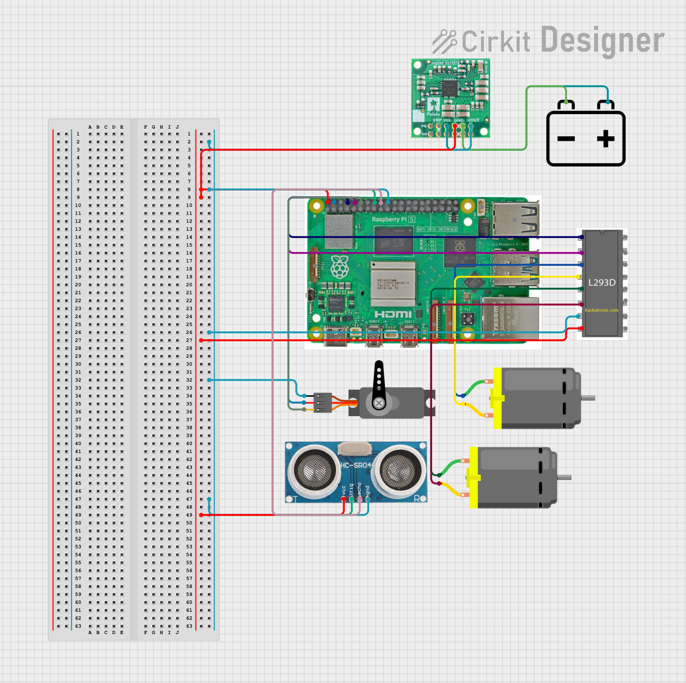
Circuit Documentation
Summary
This document provides a detailed overview of a circuit that integrates a Raspberry Pi 5, a motor driver, two DC motors, a servo motor, an ultrasonic sensor, a 12V battery, and a 5V step-down voltage regulator. The Raspberry Pi 5 serves as the central microcontroller, controlling the motors and sensors to perform various tasks. The circuit is designed to measure distance using the ultrasonic sensor and control the motors and servo based on the measured distance.
Component List
Raspberry Pi 5
- Description: A powerful single-board computer used as the main microcontroller.
- Pins: Type-C, Micro HDMI 1, Micro HDMI 2, Camera 1, Camera 2, PoE, Fan, PCIe, USB 3.0, USB 2.0, Ethernet, 5V, GND, 3.3v, GPIO 14, GPIO 15, GPIO 18, GPIO 23, GPIO 24, GPIO 25, GPIO 8, GPIO 7, GPIO 1, GPIO 12, GPIO 16, GPIO 20, GPIO 21, GPIO 2, GPIO 3, GPIO 4, GPIO 17, GPIO 27, GPIO 22, GPIO 10, GPIO 9, GPIO 11, GPIO 0, GPIO 5, GPIO 6, GPIO 13, GPIO 19, GPIO 26
Motor Driver
- Description: A component used to control the direction and speed of the DC motors.
- Pins: pin 1, pin 2, pin 3, pin 4, pin 5, pin 6, pin 7, pin 8, pin 9, pin 10, pin 11, pin 12, pin 13, pin 14, pin 15, pin 16
DC Motor (Motor 1)
- Description: A motor that converts electrical energy into mechanical motion.
- Pins: pin 1, pin 2
DC Motor (Motor 2)
- Description: A motor that converts electrical energy into mechanical motion.
- Pins: pin 1, pin 2
Servo
- Description: A motor used for precise control of angular position.
- Pins: GND, VCC, PWM
Ultrasonic Sensor
- Description: A sensor used to measure distance by using ultrasonic waves.
- Pins: +VCC, Trigger, Echo, GND
12V Battery
- Description: A power source providing 12V DC.
- Pins: -, +
5V, 5.5A Step-Down Voltage Regulator D36V50F5
- Description: A voltage regulator that steps down 12V to 5V.
- Pins: PG, EN, VRP, VIN, GND, VOUT
Wiring Details
Raspberry Pi 5
- 5V connected to GND of the 5V, 5.5A Step-Down Voltage Regulator D36V50F5
- 5V connected to VCC of the Servo
- GND connected to VOUT of the 5V, 5.5A Step-Down Voltage Regulator D36V50F5
- GPIO 14 connected to pin 1 of the Motor Driver
- GPIO 15 connected to pin 2 of the Motor Driver
- GPIO 18 connected to PWM of the Servo
- GPIO 23 connected to Trigger of the Ultrasonic Sensor
- GPIO 24 connected to Echo of the Ultrasonic Sensor
Motor Driver
- pin 1 connected to GPIO 14 of the Raspberry Pi 5
- pin 2 connected to GPIO 15 of the Raspberry Pi 5
- pin 3 connected to pin 1 of DC Motor (Motor 1)
- pin 4 connected to pin 2 of DC Motor (Motor 1)
- pin 5 connected to pin 1 of DC Motor (Motor 2)
- pin 6 connected to pin 2 of DC Motor (Motor 2)
- pin 7 connected to GND of the 5V, 5.5A Step-Down Voltage Regulator D36V50F5
- pin 8 connected to GND of the Raspberry Pi 5
DC Motor (Motor 1)
- pin 1 connected to pin 3 of the Motor Driver
- pin 2 connected to pin 4 of the Motor Driver
DC Motor (Motor 2)
- pin 1 connected to pin 5 of the Motor Driver
- pin 2 connected to pin 6 of the Motor Driver
Servo
- GND connected to GND of the 5V, 5.5A Step-Down Voltage Regulator D36V50F5
- VCC connected to 5V of the Raspberry Pi 5
- PWM connected to GPIO 18 of the Raspberry Pi 5
Ultrasonic Sensor
- +VCC connected to GND of the 5V, 5.5A Step-Down Voltage Regulator D36V50F5
- Trigger connected to GPIO 23 of the Raspberry Pi 5
- Echo connected to GPIO 24 of the Raspberry Pi 5
- GND connected to GND of the 5V, 5.5A Step-Down Voltage Regulator D36V50F5
12V Battery
- - connected to GND of the 5V, 5.5A Step-Down Voltage Regulator D36V50F5
- + connected to VIN of the 5V, 5.5A Step-Down Voltage Regulator D36V50F5
5V, 5.5A Step-Down Voltage Regulator D36V50F5
- VOUT connected to GND of the Raspberry Pi 5
- GND connected to 5V of the Raspberry Pi 5
- GND connected to - of the 12V Battery
- VIN connected to + of the 12V Battery
Code Documentation
Raspberry Pi 5 Code
import RPi.GPIO as GPIO
import time

# Pin Definitions
MOTOR_DRIVER_PIN1 = 14
MOTOR_DRIVER_PIN2 = 15
SERVO_PIN = 18
ULTRASONIC_TRIGGER_PIN = 23
ULTRASONIC_ECHO_PIN = 24
MOTOR1_PIN1 = 3
MOTOR1_PIN2 = 4
MOTOR2_PIN1 = 5
MOTOR2_PIN2 = 6

# Setup
GPIO.setmode(GPIO.BCM)
GPIO.setup(MOTOR_DRIVER_PIN1, GPIO.OUT)
GPIO.setup(MOTOR_DRIVER_PIN2, GPIO.OUT)
GPIO.setup(SERVO_PIN, GPIO.OUT)
GPIO.setup(ULTRASONIC_TRIGGER_PIN, GPIO.OUT)
GPIO.setup(ULTRASONIC_ECHO_PIN, GPIO.IN)
GPIO.setup(MOTOR1_PIN1, GPIO.OUT)
GPIO.setup(MOTOR1_PIN2, GPIO.OUT)
GPIO.setup(MOTOR2_PIN1, GPIO.OUT)
GPIO.setup(MOTOR2_PIN2, GPIO.OUT)

# Servo Setup
servo = GPIO.PWM(SERVO_PIN, 50)  # 50Hz PWM frequency
servo.start(0)

def set_servo_angle(angle):
    duty = angle / 18 + 2
    GPIO.output(SERVO_PIN, True)
    servo.ChangeDutyCycle(duty)
    time.sleep(1)
    GPIO.output(SERVO_PIN, False)
    servo.ChangeDutyCycle(0)

def measure_distance():
    GPIO.output(ULTRASONIC_TRIGGER_PIN, True)
    time.sleep(0.00001)
    GPIO.output(ULTRASONIC_TRIGGER_PIN, False)

    start_time = time.time()
    stop_time = time.time()

    while GPIO.input(ULTRASONIC_ECHO_PIN) == 0:
        start_time = time.time()

    while GPIO.input(ULTRASONIC_ECHO_PIN) == 1:
        stop_time = time.time()

    time_elapsed = stop_time - start_time
    distance = (time_elapsed * 34300) / 2
    return distance

def move_forward():
    GPIO.output(MOTOR1_PIN1, GPIO.HIGH)
    GPIO.output(MOTOR1_PIN2, GPIO.LOW)
    GPIO.output(MOTOR2_PIN1, GPIO.HIGH)
    GPIO.output(MOTOR2_PIN2, GPIO.LOW)

def move_backward():
    GPIO.output(MOTOR1_PIN1, GPIO.LOW)
    GPIO.output(MOTOR1_PIN2, GPIO.HIGH)
    GPIO.output(MOTOR2_PIN1, GPIO.LOW)
    GPIO.output(MOTOR2_PIN2, GPIO.HIGH)

def stop_m