Cirkit Designer
Your all-in-one circuit design IDE
Home /
Project Documentation
Arduino UNO Based Temperature Monitoring with OLED Display and Fan Control

Circuit Documentation
Summary
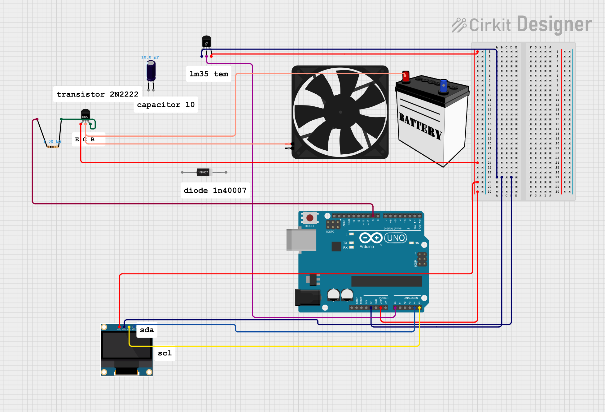
The circuit in question is designed to interface an Arduino UNO with a temperature sensor (LM35), an OLED display, and a fan controlled by an NPN transistor. The temperature sensor provides analog temperature readings to the Arduino, which can be displayed on the OLED. The fan is controlled through a transistor switched by a digital output from the Arduino, allowing for on/off control. The circuit is powered by a 12V battery, and the Arduino regulates the voltage for its peripherals.
Component List
Arduino UNO
- Microcontroller board based on the ATmega328P
- Provides I/O pins for interfacing with various sensors and peripherals
- Includes power supply pins and analog/digital I/O
Temperature Sensor (LM35)
- Analog temperature sensor with a linear voltage output proportional to the Celsius temperature
- Requires a power supply and outputs a temperature-dependent voltage
0.96" OLED Display
- Small display for showing data such as sensor readings
- Communicates with the Arduino via I2C (uses SCK and SDA lines)
NPN-Transistor
- Acts as a switch to control the power to the fan
- Controlled by an output pin from the Arduino
1N4007 Rectifier Diode
- Used for protecting the circuit from reverse voltage transients
Electrolytic Capacitor
- Provides decoupling for the power supply
- Capacitance: 0.00001 Farads
12V Battery
- Provides the power source for the circuit
Fan
- An electric fan to be controlled by the circuit
- Operates at 5V
Resistor
- Limits the current flowing into the base of the NPN transistor
- Resistance: 1000 Ohms
Wiring Details
Arduino UNO
- 5V pin connected to the power supply pins (+Vs) of the Temperature Sensor and VDD of the OLED
- GND pin connected to the ground pins (GND) of the Temperature Sensor, OLED, and Emitter (E) of the NPN-Transistor
- A0 pin connected to the Vout pin of the Temperature Sensor for analog temperature readings
- A4 (SDA) and A5 (SCL) pins connected to the SDA and SCK pins of the OLED for I2C communication
- D9 pin connected to one end of the Resistor
Temperature Sensor (LM35)
- +Vs pin connected to the 5V output from the Arduino
- GND pin connected to the ground of the Arduino
- Vout pin connected to the A0 pin of the Arduino for temperature measurement
0.96" OLED
- VDD pin connected to the 5V output from the Arduino
- GND pin connected to the ground of the Arduino
- SCK pin connected to the A5 pin of the Arduino for I2C clock
- SDA pin connected to the A4 pin of the Arduino for I2C data
NPN-Transistor
- Emitter (E) connected to the ground of the Arduino
- Collector (C) connected to the 12V battery and the 5V pin of the Fan
- Base (B) connected to the other end of the Resistor
Fan
- 5V pin connected to the Collector (C) of the NPN-Transistor
- GND pin connected to the ground of the Arduino
Resistor
- One end connected to the D9 pin of the Arduino
- The other end connected to the Base (B) of the NPN-Transistor
Documented Code
Arduino UNO Code (sketch.ino)
void setup() {
  // put your setup code here, to run once:

}

void loop() {
  // put your main code here, to run repeatedly:

}
Note: The provided code is a template and does not include specific functionality. It should be populated with the setup and loop routines required to read the temperature sensor, control the OLED display, and manage the fan via the NPN transistor.