Cirkit Designer
Your all-in-one circuit design IDE
Home /
Project Documentation
Arduino-Controlled Servo with Ultrasonic Distance Sensing
Circuit Documentation
Summary
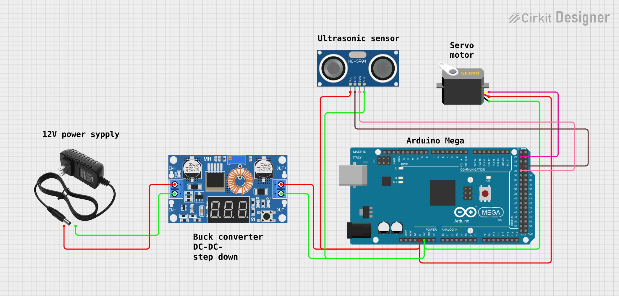
This document provides a detailed overview of a circuit designed to interface an Arduino Mega 2560 with a servo motor, an HC-SR04 ultrasonic sensor, and a step-down (buck) converter module (XL4015 5A DC) powered by a 12V power supply. The Arduino Mega 2560 controls the servo motor and reads distance measurements from the ultrasonic sensor. The step-down converter is used to regulate the voltage from the 12V power supply to a level suitable for powering the servo and the sensor.
Component List
Servo
- Description: A motor capable of precise position control.
- Pins: gnd, vcc, pulse
12V Power Supply
- Description: Provides a 12V voltage source for the circuit.
- Pins: +, -
XL4015 5A DC Buck Step-down Converter
- Description: Reduces the input voltage to a lower output voltage.
- Pins: Output +, Output -, Input +, Input -
HC-SR04 Ultrasonic Sensor
- Description: Measures distances by emitting ultrasonic waves and measuring the time taken for the echo to return.
- Pins: VCC, TRIG, ECHO, GND
Arduino Mega 2560
- Description: A microcontroller board based on the ATmega2560, with numerous digital and analog I/O pins.
- Pins: Multiple digital and analog pins, including IOREF, RESET, 3V3, 5V, GND, VIN, A0-A15, D0-D53, AREF, SDA, SCL
Wiring Details
Servo
- Ground: Connected to Arduino Mega 2560 GND
- VCC: Connected to the output of the XL4015 5A DC Buck Step-down Converter
- Pulse: Controlled by Arduino Mega 2560 pin D22
12V Power Supply
- + (Positive): Connected to the input of the XL4015 5A DC Buck Step-down Converter
- - (Negative): Connected to the input of the XL4015 5A DC Buck Step-down Converter
XL4015 5A DC Buck Step-down Converter
- Output +: Connected to the VCC of both the Servo and the HC-SR04 Ultrasonic Sensor
- Output -: Connected to the GND of both the Servo and the HC-SR04 Ultrasonic Sensor
- Input +: Connected to the + of the 12V Power Supply
- Input -: Connected to the - of the 12V Power Supply
HC-SR04 Ultrasonic Sensor
- VCC: Connected to the output of the XL4015 5A DC Buck Step-down Converter
- TRIG: Controlled by Arduino Mega 2560 pin D26
- ECHO: Connected to Arduino Mega 2560 pin D28
- GND: Connected to Arduino Mega 2560 GND
Arduino Mega 2560
- 5V: Provides power to the XL4015 5A DC Buck Step-down Converter
- GND: Common ground for the circuit
- D22: Controls the Servo pulse
- D26: Sends trigger signal to HC-SR04 Ultrasonic Sensor
- D28: Receives echo signal from HC-SR04 Ultrasonic Sensor
Documented Code
Arduino Mega 2560 Code
void setup() {
  // put your setup code here, to run once:

}

void loop() {
  // put your main code here, to run repeatedly:

}
Note: The provided code is a template and does not contain specific functionality. It should be populated with the setup and loop routines required to control the servo and read data from the ultrasonic sensor.