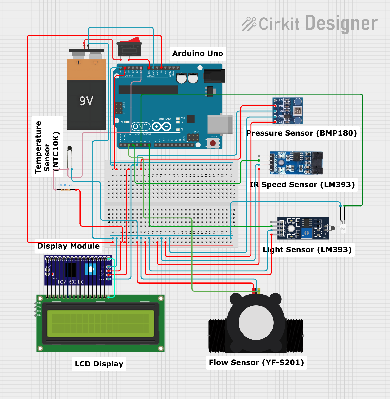
Arduino UNO-Based Environmental Monitoring System with LCD Display

Circuit Documentation
Summary
This document provides a detailed overview of an electronic circuit designed to interface various sensors and components with an Arduino UNO microcontroller. The circuit includes a water flow meter, temperature sensor, barometric pressure sensor, an I2C LCD screen, a resistor, a 9V battery, a rocker switch, and an LED. The Arduino UNO serves as the central processing unit, reading sensor data and controlling the LCD display and LED. The circuit is powered by a 9V battery, with a rocker switch to control power flow. Communication with the LCD and BMP180 barometric sensor is achieved via the I2C protocol.
Component List
- YF-S201 Water Flow Meter: A device that measures the rate of water flow.
- Sensor NTC LM393: A temperature sensor module based on the LM393 comparator.
- NTC: A thermistor used for temperature sensing.
- Arduino UNO: A microcontroller board based on the ATmega328P.
- I2C LCD 16x2 Screen: A liquid crystal display that communicates over the I2C bus.
- BMP180: A digital barometric pressure sensor that also communicates over I2C.
- Resistor (10k Ohms): A passive component used to limit current or divide voltages.
- Battery 9V: A power source for the circuit.
- Rocker Switch: A switch to control the power supply to the circuit.
- LCM1602 IIC: An I2C interface module for the LCD screen.
- LM393: A dual differential comparator integrated circuit.
- LED (white): A light-emitting diode used as an indicator.
Wiring Details
YF-S201 Water Flow Meter
- SIG connected to Arduino UNO Pin D2
- GND connected to common ground
- VCC connected to Arduino UNO 5V
Sensor NTC LM393
- A0 not connected
- D0 connected to Arduino UNO Pin D7
- GND connected to common ground
- VCC connected to Arduino UNO 5V
NTC
- A0 connected to Arduino UNO Pin A0
- A1 connected to common ground
Arduino UNO
- 5V connected to various components for power
- GND connected to common ground and various components
- A0 connected to NTC A0
- A4 connected to I2C SDA line
- A5 connected to I2C SCL line
- D2 connected to YF-S201 Water Flow Meter SIG
- D3 connected to LM393 D0
- D5 connected to LED cathode
- D7 connected to Sensor NTC LM393 D0
- Vin connected to Rocker Switch
I2C LCD 16x2 Screen
- SCL connected to Arduino UNO A5
- SDA connected to Arduino UNO A4
- VCC (5V) connected to Arduino UNO 5V
- GND connected to common ground
BMP180
- 3.3 not connected
- SDA connected to Arduino UNO A4
- SCL connected to Arduino UNO A5
- GND connected to common ground
- VCC connected to Arduino UNO 5V
Resistor (10k Ohms)
- pin1 connected to Arduino UNO A0
- pin2 connected to Arduino UNO 5V
Battery 9V
- VCC connected to Rocker Switch
- GND connected to common ground
Rocker Switch
- 1 connected to Battery 9V VCC
- 2 connected to Arduino UNO Vin
LM393
- VCC connected to Arduino UNO 5V
- GND connected to common ground
- D0 connected to Arduino UNO D3
- A0 not connected
LED (white)
- cathode connected to Arduino UNO D5
- anode connected to common ground
Documented Code
Arduino UNO Code (sketch.ino)
void setup() {
  // put your setup code here, to run once:

}

void loop() {
  // put your main code here, to run repeatedly:

}
Note: The provided code is a template and does not include specific functionality. It needs to be populated with the logic to initialize and read from the connected sensors, control the LCD display, and manage the LED state.