Cirkit Designer
Your all-in-one circuit design IDE
Home /
Project Documentation
ESP32 CAM Wi-Fi Enabled Camera Module with USB Power

Circuit Documentation
Summary
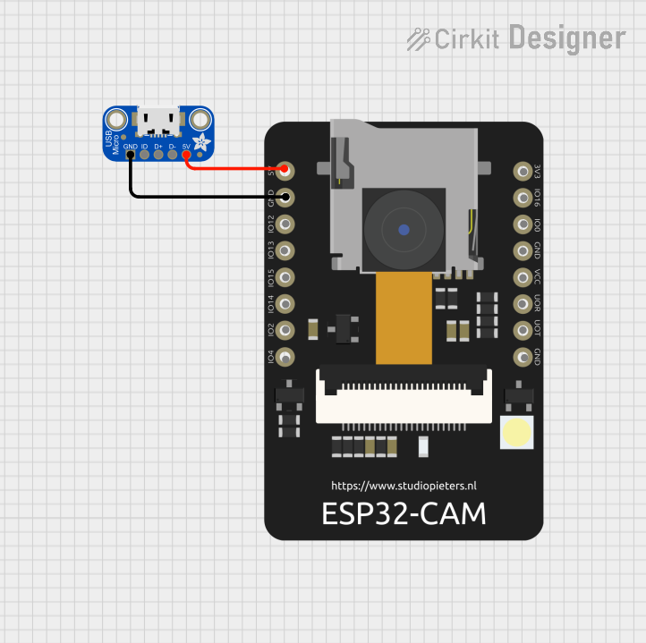
This document provides a detailed overview of a circuit that includes an ESP32 CAM module and an Adafruit Micro USB Breakout board. The circuit is designed to power the ESP32 CAM using the USB breakout board. The document includes a list of components, wiring details, and any associated code.
Component List
ESP32 CAM
- Description: The ESP32 CAM is a Wi-Fi and Bluetooth-enabled microcontroller with an integrated camera module. It is commonly used for IoT applications, including video streaming and image processing.
- Pins:
- 5V
- GND
- GPIO12
- GPIO13
- GPIO15
- GPIO14
- GPIO2
- GPIO4
- 3.3V
- GPIO16
- GPIO0
- 3.3V / 5V / P_OUT
- GPIO3 / RX
- GPIO1 / TX
Adafruit Micro USB Breakout
- Description: The Adafruit Micro USB Breakout board is used to easily connect USB power and data lines to a circuit. It breaks out the USB pins to more accessible headers.
- Pins:
- GND
- ID
- D+
- D-
- VBUS
Wiring Details
ESP32 CAM
- 5V: Connected to VBUS of Adafruit Micro USB Breakout
- GND: Connected to GND of Adafruit Micro USB Breakout
Adafruit Micro USB Breakout
- VBUS: Connected to 5V of ESP32 CAM
- GND: Connected to GND of ESP32 CAM
Code
There is no code associated with this circuit.
This document provides a comprehensive overview of the circuit, including the components used and their interconnections. The ESP32 CAM is powered by the Adafruit Micro USB Breakout board, with the 5V and GND pins connected accordingly.