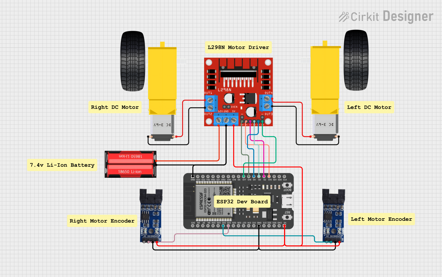
ESP32-Controlled Dual DC Motor Driver with Optical Encoder Feedback

Circuit Documentation
Summary
This circuit is designed to control a pair of DC gearmotors with optical encoder feedback for speed and position sensing. The core of the circuit is an ESP32 microcontroller, which interfaces with an L298N DC motor driver to control the speed and direction of the motors. The optical encoder sensors provide feedback to the ESP32, which can be used for precise control of the motors. The power is supplied by an 18650 Li-Ion battery, which provides the necessary voltage to the motor driver and the microcontroller through a voltage regulation system.
Component List
L298N DC Motor Driver
- Description: A motor driver module capable of driving two DC motors.
- Pins: OUT1, OUT2, 12V, GND, 5V, OUT3, OUT4, 5V-ENA-JMP-I, 5V-ENA-JMP-O, +5V-J1, +5V-J2, ENA, IN1, IN2, IN3, IN4, ENB
Gearmotor DC Wheels (Left and Right)
- Description: DC gearmotors used for the wheels of a mobile platform.
- Pins: PIN1, PIN2
18650 Li-Ion Battery
- Description: A rechargeable lithium-ion battery providing power to the circuit.
- Pins: Positive, Negative
ESP32 - 38 Pins
- Description: A microcontroller with Wi-Fi and Bluetooth capabilities.
- Pins: 3V3, EN, SP, SN, G34, G35, G32, G33, G25, G26, G27, G14, G12, GND, G13, SD2, SD3, CMD, 5V, G23, G22, TXD, RXD, G21, G19, G18, G5, G17, G16, G4, G0, G2, G15, SD1, SD0, CLK
Optical Encoder Sensor Module
- Description: Sensor modules used to detect the rotational position of the gearmotor shafts.
- Pins: A0, D0, GND, VCC
Wiring Details
L298N DC Motor Driver
- 5V: Connected to ESP32 (5V) and both Optical Encoder Sensor Modules (VCC).
- GND: Common ground with ESP32, Optical Encoder Sensor Modules, and 18650 Li-Ion battery.
- 12V: Connected to the 18650 Li-Ion battery (Positive).
- ENA, ENB: Controlled by ESP32 (G16, G17).
- IN1, IN2, IN3, IN4: Controlled by ESP32 (G15, G2, G0, G4).
- OUT1, OUT2: Connected to Gearmotor DC Wheels Right (PIN2, PIN1).
- OUT3, OUT4: Connected to Gearmotor DC Wheels Left (PIN2, PIN1).
Gearmotor DC Wheels (Left and Right)
- PIN1, PIN2: Connected to the corresponding OUT pins on the L298N DC Motor Driver.
18650 Li-Ion Battery
- Positive: Connected to L298N DC Motor Driver (12V).
- Negative: Common ground with ESP32 and L298N DC Motor Driver.
ESP32 - 38 Pins
- GND: Common ground with all GND connections in the circuit.
- 5V: Provides power to the Optical Encoder Sensor Modules and L298N DC Motor Driver.
- G32, G33: Receive signals from Optical Encoder Sensor Modules (D0).
- G16, G17, G15, G2, G0, G4: Control signals for L298N DC Motor Driver (ENA, ENB, IN1, IN2, IN3, IN4).
Optical Encoder Sensor Modules
- VCC: Connected to ESP32 (5V) and L298N DC Motor Driver (5V).
- GND: Common ground with ESP32 and L298N DC Motor Driver.
- D0: Signal output to ESP32 (G32, G33).
Documented Code
There is no code provided for the microcontroller. The code would typically include initialization of the GPIO pins, setup of PWM channels for motor speed control, and interrupt service routines for handling the encoder signals. It would also include the main control loop where the logic for motor control based on encoder feedback would be implemented.