
Circuit Documentation
Summary of the Circuit
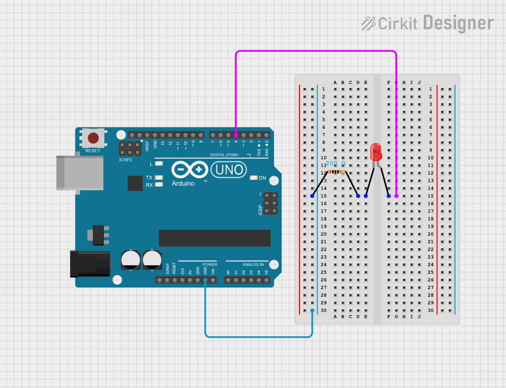
This circuit consists of an Arduino UNO microcontroller, a red two-pin LED, and a resistor. The purpose of the circuit is to blink the LED on and off at a regular interval of one second. The Arduino UNO is programmed to control the LED state using one of its digital I/O pins. The resistor is used to limit the current flowing through the LED to prevent damage.
Component List
Arduino UNO
- Description: A microcontroller board based on the ATmega328P.
- Pins Used: D4, GND.
LED: Two Pin (red)
- Description: A basic red light-emitting diode.
- Pins Used: Anode, Cathode.
Resistor
- Description: A passive two-terminal electrical component that implements electrical resistance as a circuit element.
- Resistance: 200 Ohms.
Wiring Details
Arduino UNO
- D4: Connected to the anode of the LED.
- GND: Connected to pin1 of the Resistor.
LED: Two Pin (red)
- Anode: Connected to D4 of the Arduino UNO.
- Cathode: Connected to pin2 of the Resistor.
Resistor
- Pin1: Connected to GND of the Arduino UNO.
- Pin2: Connected to the cathode of the LED.
Documented Code
Arduino UNO Code (sketch.ino)
// Pin number for the LED
const int ledPin = 13;  // You can change this to whatever pin you connect the LED to

void setup() {
  // Initialize the LED pin as an output
  pinMode(ledPin, OUTPUT);
}

void loop() {
  // Turn the LED on
  digitalWrite(ledPin, HIGH);
  // Wait for 1000 milliseconds (1 second)
  delay(1000);

  // Turn the LED off
  digitalWrite(ledPin, LOW);
  // Wait for another 1000 milliseconds (1 second)
  delay(1000);
}
Note: The code provided is set to blink an LED connected to pin D13. However, the circuit wiring indicates that the LED is connected to pin D4. To align the code with the circuit design, the ledPin variable should be changed from 13 to 4.
const int ledPin = 4; // Correct pin number for the LED
This concludes the documentation for the given circuit. The circuit is designed to blink an LED using an Arduino UNO, with a resistor to limit the current. The code provided should be updated to reflect the correct pin usage as per the circuit design.