
Arduino Mega 2560 Based Autonomous Vehicle with GPS, LoRa Communication, and Ultrasonic Sensing
View and Edit Project In Cirkit Designer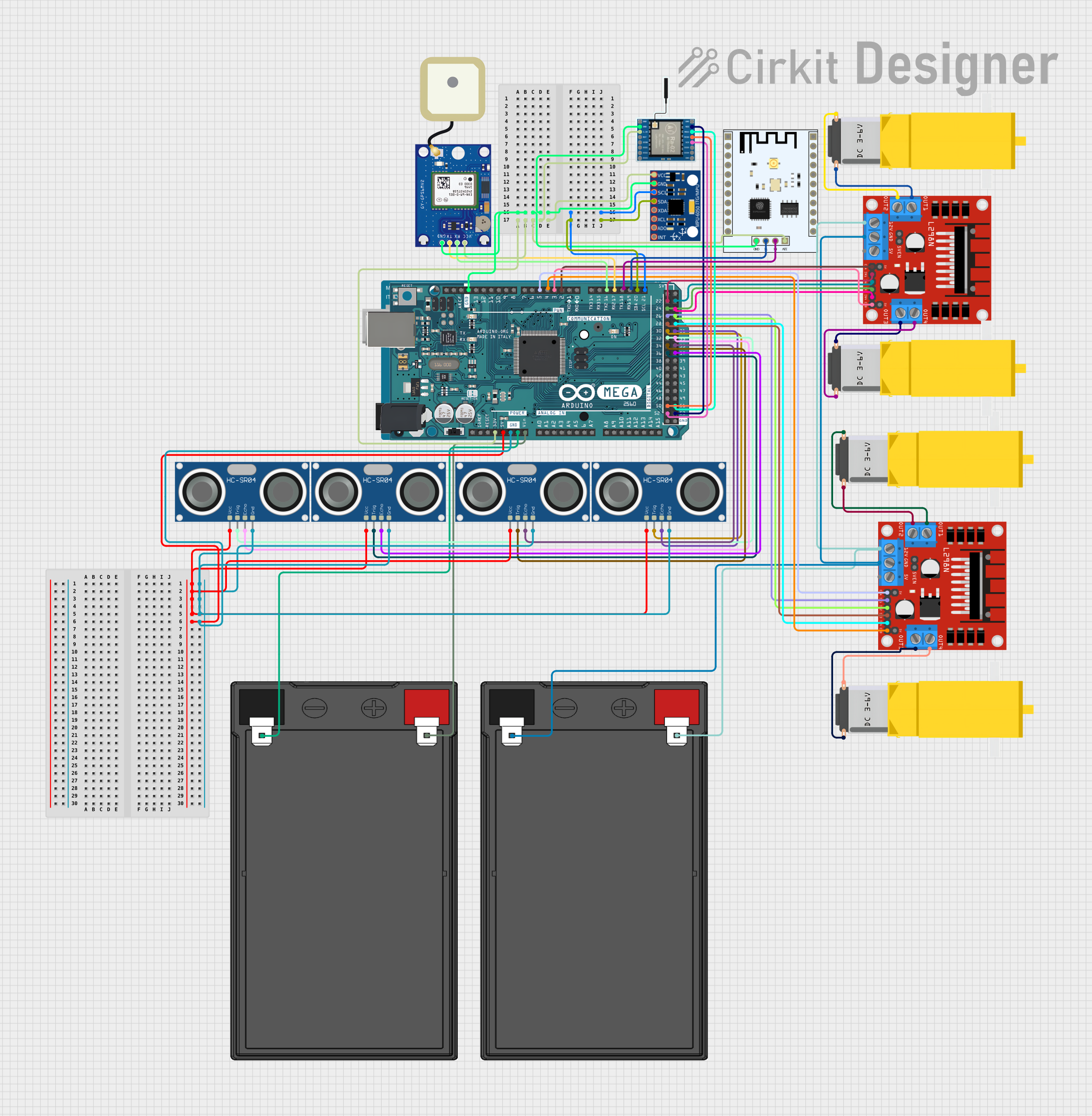
Circuit Documentation
Summary
The circuit in question is a complex system that incorporates multiple Arduino Mega 2560 microcontrollers, L298N DC motor drivers, gearmotors, a GPS module, an MPU-6050 sensor, an ESP8266 WiFi module, LoRa communication modules, HC-SR04 ultrasonic sensors, and power sources. The circuit is designed to control and power DC motors, gather sensor data, and communicate over WiFi and LoRa networks. It also includes GPS functionality for location tracking.
Component List
Microcontrollers
- Arduino Mega 2560: A microcontroller board based on the ATmega2560, with numerous digital and analog I/O pins, communication interfaces, and a USB connection for programming and serial communication.
Motor Drivers
- L298N DC Motor Driver: A high-power motor driver capable of driving up to two DC motors. It includes features like speed control and direction control pins.
Motors
- Gearmotor DC / Motorreductor: A DC motor with a gearbox attached to increase torque output.
Sensors
- HC-SR04 Ultrasonic Sensor: An ultrasonic distance sensor that can measure distances by emitting ultrasonic waves and measuring the time it takes for the echo to return.
- GPS NEO-6M V2: A GPS module that provides location data.
- MPU-6050: A motion processing unit that includes a 3-axis gyroscope and a 3-axis accelerometer.
Communication Modules
- LoRa Ra-02 SX1278: A long-range communication module based on LoRa technology.
- ESP8266 ESP-201 WiFi Module: A WiFi module that enables microcontrollers to connect to a wireless network.
Power Sources
- 12v 7ah Battery: A rechargeable battery that provides a 12V power supply.
Wiring Details
Arduino Mega 2560
- 5V Pin: Connected to the VCC of GPS NEO-6M V2, MPU-6050, ESP8266 WiFi Module, LoRa Ra-02 SX1278, and HC-SR04 Ultrasonic Sensors.
- VIN Pin: Connected to the positive terminal of a 12v 7ah Battery.
- GND Pin: Common ground for the GPS NEO-6M V2, MPU-6050, ESP8266 WiFi Module, LoRa Ra-02 SX1278, and HC-SR04 Ultrasonic Sensors.
- Digital Pins: Connected to various control pins of the L298N DC motor drivers, HC-SR04 Ultrasonic Sensors, and communication modules for control and data transfer.
L298N DC Motor Driver
- 12V Pin: Connected to the positive terminal of a 12v 7ah Battery.
- GND Pin: Connected to the negative terminal of a 12v 7ah Battery.
- Motor Output Pins (OUT1, OUT2, OUT3, OUT4): Connected to the corresponding pins of the Gearmotor DC / Motorreductor.
- Control Pins (ENA, ENB, IN1, IN2, IN3, IN4): Connected to various PWM and digital pins of the Arduino Mega 2560 for motor speed and direction control.
Gearmotor DC / Motorreductor
- Pin1 and Pin2: Connected to the motor output pins of the L298N DC motor drivers.
GPS NEO-6M V2
- TX and RX Pins: Connected to the corresponding RX and TX pins of the Arduino Mega 2560 for serial communication.
MPU-6050
- SCL and SDA Pins: Connected to the corresponding SCL and SDA pins of the Arduino Mega 2560 for I2C communication.
LoRa Ra-02 SX1278
- SCK, MISO, MOSI, NSS Pins: Connected to the corresponding SPI pins of the Arduino Mega 2560 for SPI communication.
ESP8266 ESP-201 WiFi Module
- TX and RX Pins: Connected to the corresponding RX and TX pins of the Arduino Mega 2560 for serial communication.
HC-SR04 Ultrasonic Sensor
- TRIG and ECHO Pins: Connected to the corresponding digital pins of the Arduino Mega 2560 for triggering the ultrasonic pulse and reading the echo.
Documented Code
Arduino Mega 2560 (Main Controller)
void setup() {
  // put your setup code here, to run once:

}

void loop() {
  // put your main code here, to run repeatedly:

}
Note: The above code is a template and does not include specific functionality. Each Arduino Mega 2560 in the system would have similar code structures tailored to their specific tasks within the circuit.
The provided code snippets are placeholders and do not represent the actual operational code required to control the components within the circuit. The actual code would need to be developed to handle tasks such as motor control, sensor data acquisition, communication, and GPS tracking.