
ESP32-Controlled Automated Plant Watering System with Humidity Sensing and RGB Indicator
View and Edit Project In Cirkit Designer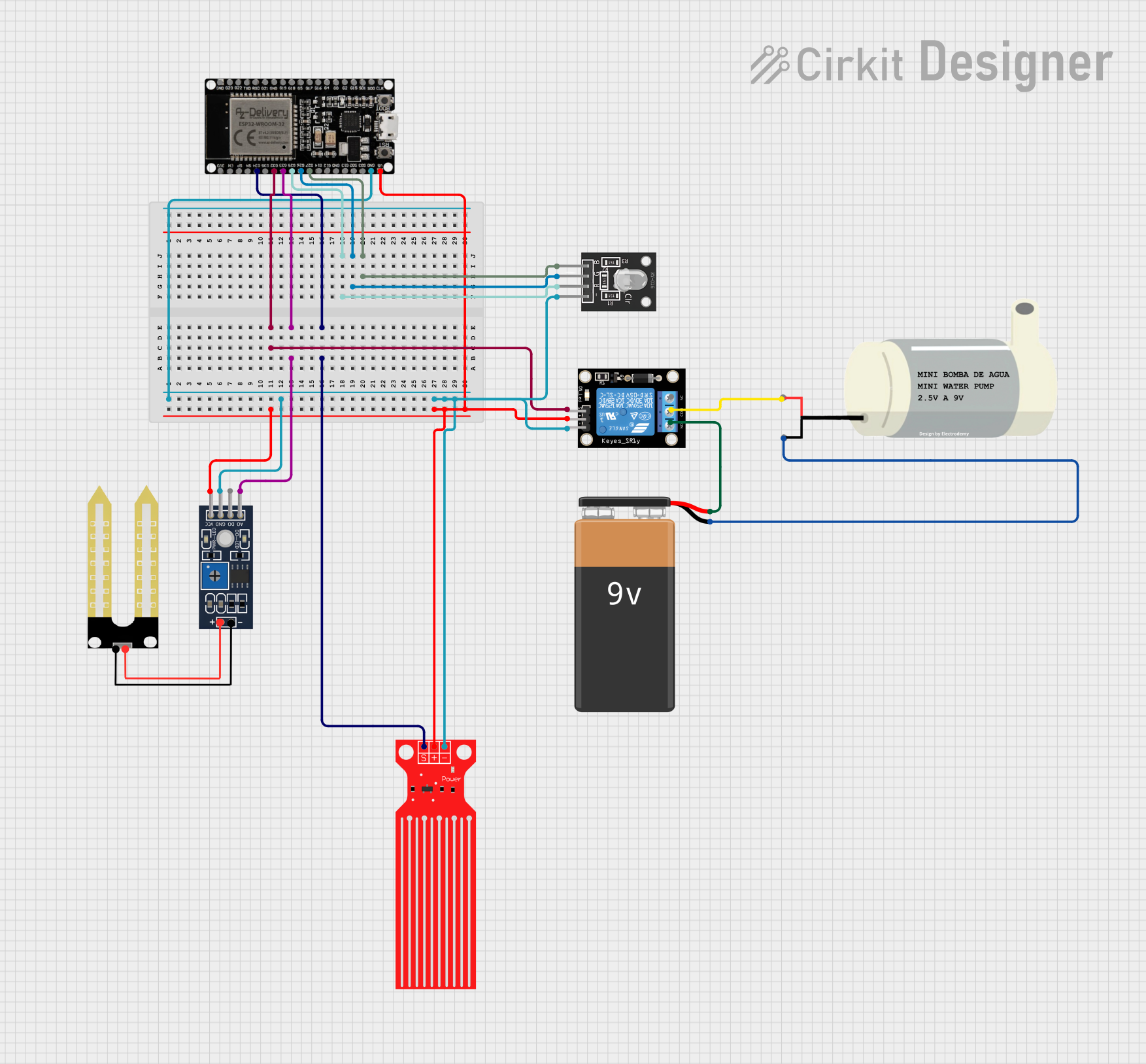
Circuit Documentation
Summary
This circuit is designed to interface an ESP32 microcontroller with various sensors and actuators, including a humidity sensor (YL-69), a water level sensor, an RGB LED (KY-016), a relay module (KY-019), and a mini water pump. The ESP32 controls the relay, which in turn controls the power to the mini water pump. The sensors provide environmental feedback to the ESP32, which can then adjust the system's behavior accordingly. The RGB LED serves as an indicator. The circuit is powered by a 9V battery.
Component List
ESP32 38 PINS
- Microcontroller with WiFi and Bluetooth capabilities.
- It has a variety of GPIO pins for interfacing with other components.
Mini Water Pump
- A small pump used for moving water.
- It operates on a voltage provided by the relay module.
Humidity Sensor (YL-69)
- A sensor for detecting the humidity of the soil.
- It provides both analog and digital outputs.
KY-016 RGB LED
- A multicolor LED that can display a variety of colors.
- It has separate pins for red, green, and blue control.
9V Battery
- A standard 9V battery used to provide power to the circuit.
KY-019 Relay Module 1 Channel
- A single-channel relay module that can control high-power devices.
- It has normally open (NO) and normally closed (NC) contacts.
Water Level Sensor
- A sensor used to detect the level of water in a container.
- It provides a signal that can be read by the microcontroller.
Wiring Details
ESP32 38 PINS
- GND: Connected to the ground plane.
- G32: Connected to the signal pin (S) of the KY-019 Relay module.
- 33: Connected to the analog output (A0) of the Humidity YL-69 sensor.
- G34: Connected to the signal (SIG) pin of the Water Level Sensor.
- G25, G26, G27: Connected to the red (R), green (G), and blue (B) pins of the KY-016 RGB LED, respectively.
- 5V: Connected to the VCC pins of the Humidity YL-69 sensor, KY-019 Relay module, and Water Level Sensor.
Mini Water Pump
- VCC: Connected to the common (COM) pin of the KY-019 Relay module.
- GND: Connected to the negative terminal (-) of the 9V Battery.
Humidity Sensor (YL-69)
- A0: Connected to pin 33 of the ESP32.
- GND: Connected to the ground plane.
- VCC: Connected to the 5V pin of the ESP32.
KY-016 RGB LED
- R: Connected to pin G25 of the ESP32.
- G: Connected to pin G26 of the ESP32.
- B: Connected to pin G27 of the ESP32.
- GND: Connected to the ground plane.
9V Battery
- -: Connected to the ground plane.
- +: Connected to the normally open (NO) contact of the KY-019 Relay module.
KY-019 Relay Module 1 Channel
- S: Connected to pin G32 of the ESP32.
- 5V: Connected to the 5V pin of the ESP32.
- GND: Connected to the ground plane.
- NC: Not connected in this circuit.
- COM: Connected to the VCC pin of the Mini Water Pump.
- NO: Connected to the positive terminal (+) of the 9V Battery.
Water Level Sensor
- SIG: Connected to pin G34 of the ESP32.
- VCC: Connected to the 5V pin of the ESP32.
- GND: Connected to the ground plane.
Documented Code
Since no code was provided, this section is left blank. The code for the ESP32 would typically include initialization of the GPIO pins, reading sensor data, controlling the RGB LED, and activating the relay to power the mini water pump based on sensor inputs.