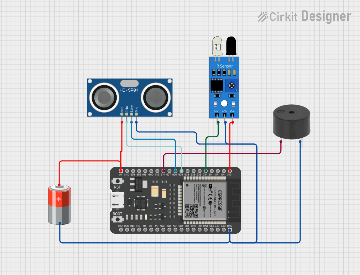
ESP32-Based Obstacle Detection System with IR and Ultrasonic Sensors

Circuit Documentation
Summary of the Circuit
This circuit integrates an ESP32 microcontroller with an IR sensor, an HC-SR04 ultrasonic sensor, a buzzer, and a 5V battery. The ESP32 serves as the central processing unit, interfacing with the sensors to receive input signals and controlling the buzzer as an output device. The IR sensor is used to detect infrared signals, which can be used for simple presence or obstacle detection. The HC-SR04 ultrasonic sensor is used for measuring distances using ultrasonic waves. The buzzer can provide audible feedback based on the inputs from the sensors. The 5V battery powers the circuit, with the ESP32 regulating the voltage for the IR sensor.
Component List
ESP32 - 38 pins
- Description: A microcontroller with Wi-Fi and Bluetooth capabilities and a wide range of GPIO pins.
- Pins: 3V3, EN, SP, SN, G34, G35, G32, G33, G25, G26, G27, G14, G12, GND, G13, SD2, SD3, CMD, 5V, G23, G22, TXD, RXD, G21, G19, G18, G5, G17, G16, G4, G0, G2, G15, SD1, SD0, CLK
IR Sensor
- Description: A sensor that detects infrared light, typically used for proximity or motion detection.
- Pins: out, gnd, vcc
HC-SR04 Ultrasonic Sensor
- Description: A sensor that measures distance by emitting ultrasonic waves and measuring the time taken for the echo to return.
- Pins: VCC, TRIG, ECHO, GND
Buzzer
- Description: An electromechanical component that produces sound when an electrical signal is applied.
- Pins: PIN, GND
5V Battery
- Description: A power source that provides a 5V supply to the circuit.
- Pins: +, -
Wiring Details
ESP32 - 38 pins
- 3V3 connected to IR Sensor VCC
- G34 connected to IR Sensor OUT
- G25 connected to HC-SR04 TRIG
- G26 connected to HC-SR04 ECHO
- G14 connected to Buzzer PIN
- 5V connected to 5V Battery +
- GND connected to common ground net (IR Sensor GND, HC-SR04 GND, Buzzer GND, 5V Battery -)
IR Sensor
- VCC connected to ESP32 3V3
- OUT connected to ESP32 G34
- GND connected to common ground net
HC-SR04 Ultrasonic Sensor
- VCC connected to 5V Battery +
- TRIG connected to ESP32 G25
- ECHO connected to ESP32 G26
- GND connected to common ground net
Buzzer
- PIN connected to ESP32 G14
- GND connected to common ground net
5V Battery
- connected to ESP32 5V and HC-SR04 VCC
- connected to common ground net
Documented Code
Since no code was provided, this section is left blank. The code for the ESP32 would typically include initialization of the GPIO pins, setup of the Wi-Fi or Bluetooth modules if used, and the main loop where the microcontroller reads sensor data, processes it, and controls the buzzer accordingly.