
ESP32-Based Smart Medication Dispenser with Wi-Fi Connectivity and RTC Scheduling
View and Edit Project In Cirkit Designer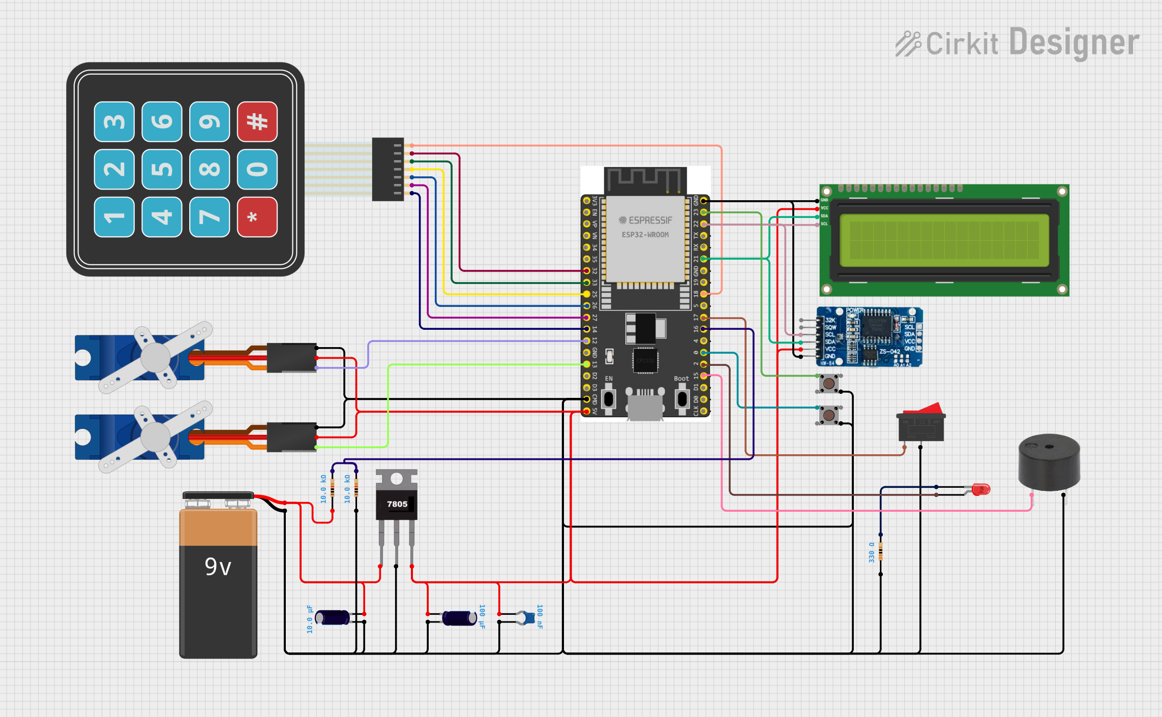
Circuit Documentation
Summary
This circuit is designed around the ESP32 Wroom Dev Kit, which serves as the central microcontroller unit (MCU) for interfacing with various peripherals including a membrane matrix keypad, an RTC (Real-Time Clock) module DS3231, an I2C LCD 16x2 screen, buzzers, pushbuttons, servos, and a set of resistors and capacitors for signal conditioning and power stabilization. The ESP32 is programmed to handle user inputs from the keypad, display information on the LCD, keep track of time with the RTC, and control output devices like buzzers and servos based on the logic defined in the embedded code.
Component List
ESP32 Wroom Dev Kit
- Microcontroller development board based on the ESP32 chip.
- Features Wi-Fi and Bluetooth connectivity.
- Provides a variety of GPIO pins for interfacing with peripherals.
Membrane Matrix Keypad
- A simple interface for user input.
- Consists of rows and columns to form a matrix of buttons.
RTC DS3231
- A highly accurate I2C real-time clock with an integrated temperature-compensated crystal oscillator (TCXO) and crystal.
I2C LCD 16x2 Screen
- An alphanumeric liquid crystal display capable of displaying 16 characters per line across 2 lines.
- Uses I2C communication protocol for interfacing with the MCU.
Buzzer
- An audio signaling device that can be used to provide audible alerts or feedback.
Pushbutton
- A simple switch mechanism for controlling some aspect of a machine or a process.
Resistor
- A passive two-terminal electrical component that implements electrical resistance as a circuit element.
Tower Pro SG90 Servo
- A small and lightweight servo motor capable of precise position control.
Electrolytic Capacitor
- A type of capacitor with a larger capacitance per unit volume than other types, used for filtering or energy storage.
Ceramic Capacitor
- A fixed-value capacitor where the ceramic material acts as the dielectric.
7805 Voltage Regulator
- A commonly used voltage regulator that outputs a stable 5V from a higher voltage input.
9V Battery
- A standard battery used for providing power to circuits.
LED: Two Pin (red)
- A basic red light-emitting diode used for indication purposes.
Rocker Switch
- A switch that rocks back and forth when pressed, typically used to toggle power on and off.
Wiring Details
ESP32 Wroom Dev Kit
GPIO 32connected to Membrane Matrix Keypad Column 2GPIO 33connected to Membrane Matrix Keypad Column 1GPIO 25connected to Membrane Matrix Keypad Row 4GPIO 26connected to Membrane Matrix Keypad Row 3GPIO 27connected to Membrane Matrix Keypad Row 2GPIO 14connected to Membrane Matrix Keypad Row 1 and Tower Pro SG90 servo SignalGPIO 13connected to Tower Pro SG90 servo SignalCMDconnected to GND netV5connected to 5V netGPIO 23connected to Pushbutton Pin 3 (out)GPIO 22connected to RTC DS3231 SCL and I2C LCD 16x2 Screen SCLGPIO 21connected to RTC DS3231 SDA and I2C LCD 16x2 Screen SDAGPIO 18connected to Membrane Matrix Keypad Column 3GPIO 17connected to Rocker Switch Pin 1GPIO 16connected to 10k Ohm Resistor pin2GPIO 0connected to Pushbutton Pin 3 (out)GPIO 2connected to LED: Two Pin (red) anodeGPIO 15connected to buzzer PINGNDconnected to GND net
Membrane Matrix Keypad
Column 2connected to ESP32 GPIO 32Column 1connected to ESP32 GPIO 33Row 4connected to ESP32 GPIO 25Row 3connected to ESP32 GPIO 26Row 2connected to ESP32 GPIO 27Row 1connected to ESP32 GPIO 14
RTC DS3231
SCLconnected to ESP32 GPIO 22SDAconnected to ESP32 GPIO 21VCCconnected to 5V netGNDconnected to GND net
I2C LCD 16x2 Screen
SCLconnected to ESP32 GPIO 22SDAconnected to ESP32 GPIO 21VCC (5V)connected to 5V netGNDconnected to GND net
Buzzer
PINconnected to ESP32 GPIO 15GNDconnected to GND net
Pushbutton
Pin 3 (out)connected to ESP32 GPIO 23 and GPIO 0Pin 2 (in)connected to GND net
Resistor (330 Ohms)
pin1connected to GND netpin2connected to LED: Two Pin (red) cathode
Tower Pro SG90 Servo
Signalconnected to ESP32 GPIO 14 and GPIO 13+5Vconnected to 5V netGNDconnected to GND net
Electrolytic Capacitor (10 µF)
+connected to 5V net-connected to GND net
Ceramic Capacitor (100 nF)
pin0connected to 5V netpin1connected to GND net
7805 Voltage Regulator
Vinconnected to 9V Battery+and Electrolytic Capacitor+Gndconnected to GND netVoutconnected to 5V net
9V Battery
+connected to 7805Vinand Electrolytic Capacitor+-connected to GND net
LED: Two Pin (red)
anodeconnected to ESP32 GPIO 2cathodeconnected to Resistor (330 Ohms)pin2
Rocker Switch
1connected to ESP32 GPIO 172connected to GND net
Documented Code
The code for the ESP32 Wroom Dev Kit is written in C++ and is designed to be compiled and uploaded using the Arduino IDE. The code includes several libraries for handling Wi-Fi connectivity, LCD display, RTC, and keypad interfacing. The code is structured into different modes, each representing a state of the system, such as setting alarms, configuring pins, and handling user input.
The code begins with the inclusion of necessary libraries and the definition of constants and global variables. It then proceeds to define functions for each mode of operation, such as MODE_0 for entering a pin, MODE_1 for the main menu, and so on. The setup() function initializes the system, setting up Wi-Fi, RTC, EEPROM, and input/output pins. The loop() function continuously checks for alarms, user input, and system state changes.
The code also includes functions for checking the entered pin (checkPin()), setting and saving alarms (saveAlarm()), triggering alarms (triggerAlarm()), and checking for missed doses (checkDose()). EEPROM is used to store and retrieve system settings and alarm times.
// Include necessary libraries
#include <WiFiManager.h>
#include <WiFi.h>
#include <LiquidCrystal_I2C.h>
#include <RTClib.h>
#include <Keypad.h>
#include "time.h"
#include <EEPROM.h>

// Define constants and global variables
#define WIFI_BUTTON 0
// ... (additional constants and variables)

// Define key mappings and initialize peripherals
char keyMap[keypadROWS][keypadCOLS] = {
  {'1','2','3',},
  // ... (additional key mappings)
};
// ... (additional initializations)

// Function prototypes
void resetInput();
void keypadEvent(KeypadEvent key);
void connectWIFI();
void MODE_0();
// ... (additional function prototypes)

// setup() function
void setup() {
  // Initialize serial communication, Wi-Fi, RTC, EEPROM, and peripherals
  Serial.begin(115200);
  // ... (additional setup code)
}

// loop() function
void loop() {
  // Check for alarms and handle system modes
  alarmTriggered = checkAlarms();
  // ... (additional loop code)
}

// Additional function implementations
void resetInput() {
  // Function to reset user input
}
// ... (additional functions)

// Main code logic for handling different modes and user interactions
// ... (complete code logic)
The provided code snippet is a simplified representation of the actual code, which includes detailed logic for handling user interactions, system states, and peripheral control. The full code should be reviewed and uploaded to the ESP32 using the Arduino IDE or a similar development environment.