
ESP32-Based Smart Power Monitoring and Control System with Relay and Current Sensors
View and Edit Project In Cirkit Designer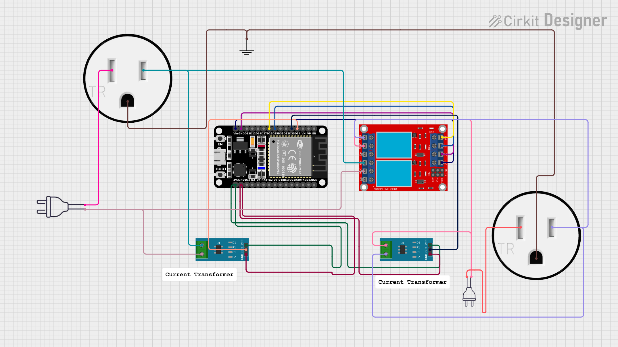
Circuit Documentation
Summary
This circuit involves an ESP32 microcontroller interfacing with two current sensors and a 2-channel relay module. The circuit also includes two 120V outlets and two 220V power sources. The ESP32 reads current values from the sensors and controls the relay module to manage the power to the outlets.
Component List
2 Channel Relay Module
- Description: A relay module with two channels, used to control high voltage devices.
- Pins: N.O. 2, COM 2, N.C. 2, N.O. 1, COM 1, N.C. 1, pin 7, pin 8, pin 9, pin 10, pin 11, pin 12, VCC+, VCC- (GND), IN 1, IN 2
Current Sensor 5A
- Description: A sensor to measure current up to 5A.
- Pins: 1, 2, GND, OUT, VCC
Power 220V
- Description: A 220V power source.
- Pins: hot wire, neutral wire
120V Outlet
- Description: A standard 120V electrical outlet.
- Pins: AC Neutral, AC Hot, GND
GND
- Description: Ground connection.
- Pins: GND
ESP32 (30 pin)
- Description: A 30-pin ESP32 microcontroller.
- Pins: EN, VP, VN, D34, D35, D32, D33, D25, D26, D27, D14, D12, D13, GND, Vin, D23, D22, TX0, RX0, D21, D19, D18, D5, TX2, RX2, D4, D2, D15, 3V3
Wiring Details
2 Channel Relay Module
- IN 1 connected to ESP32 D25
- IN 2 connected to ESP32 D26
- VCC- (GND) connected to ESP32 GND
- VCC+ connected to ESP32 Vin
- N.O. 2 connected to Current Sensor 5A 2 and 120V Outlet AC Hot
- COM 2 connected to Current Sensor 5A 1 and Power 220V hot wire
- N.O. 1 connected to Current Sensor 5A 1 and 120V Outlet AC Hot
- COM 1 connected to Current Sensor 5A 2 and Power 220V hot wire
Current Sensor 5A (Instance 1)
- OUT connected to ESP32 D34
- GND connected to ESP32 GND
- VCC connected to ESP32 3V3
- 1 connected to 2 Channel Relay Module COM 2 and Power 220V hot wire
- 2 connected to 2 Channel Relay Module N.O. 2 and 120V Outlet AC Hot
Current Sensor 5A (Instance 2)
- OUT connected to ESP32 D35
- GND connected to ESP32 GND
- VCC connected to ESP32 3V3
- 1 connected to 2 Channel Relay Module N.O. 1 and 120V Outlet AC Hot
- 2 connected to 2 Channel Relay Module COM 1 and Power 220V hot wire
Power 220V (Instance 1)
- hot wire connected to Current Sensor 5A 1 and 2 Channel Relay Module COM 2
- neutral wire connected to 120V Outlet AC Neutral
Power 220V (Instance 2)
- hot wire connected to Current Sensor 5A 2 and 2 Channel Relay Module COM 1
- neutral wire connected to 120V Outlet AC Neutral
120V Outlet (Instance 1)
- AC Neutral connected to Power 220V neutral wire
- AC Hot connected to Current Sensor 5A 2 and 2 Channel Relay Module N.O. 2
- GND connected to GND
120V Outlet (Instance 2)
- AC Neutral connected to Power 220V neutral wire
- AC Hot connected to Current Sensor 5A 1 and 2 Channel Relay Module N.O. 1
- GND connected to GND
GND
- GND connected to 120V Outlet GND
ESP32 (30 pin)
- D34 connected to Current Sensor 5A OUT
- D35 connected to Current Sensor 5A OUT
- D25 connected to 2 Channel Relay Module IN 1
- D26 connected to 2 Channel Relay Module IN 2
- GND connected to 2 Channel Relay Module VCC- (GND) and Current Sensor 5A GND
- Vin connected to 2 Channel Relay Module VCC+
- 3V3 connected to Current Sensor 5A VCC
Code
No code provided for this circuit.
This documentation provides a comprehensive overview of the circuit, including a summary, detailed component list, wiring details, and code section. Each component and its connections are clearly described to ensure proper understanding and implementation.