Cirkit Designer
Your all-in-one circuit design IDE
Home /
Project Documentation
Arduino UNO Fingerprint-Activated Solenoid Lock System
Circuit Documentation
Summary of the Circuit
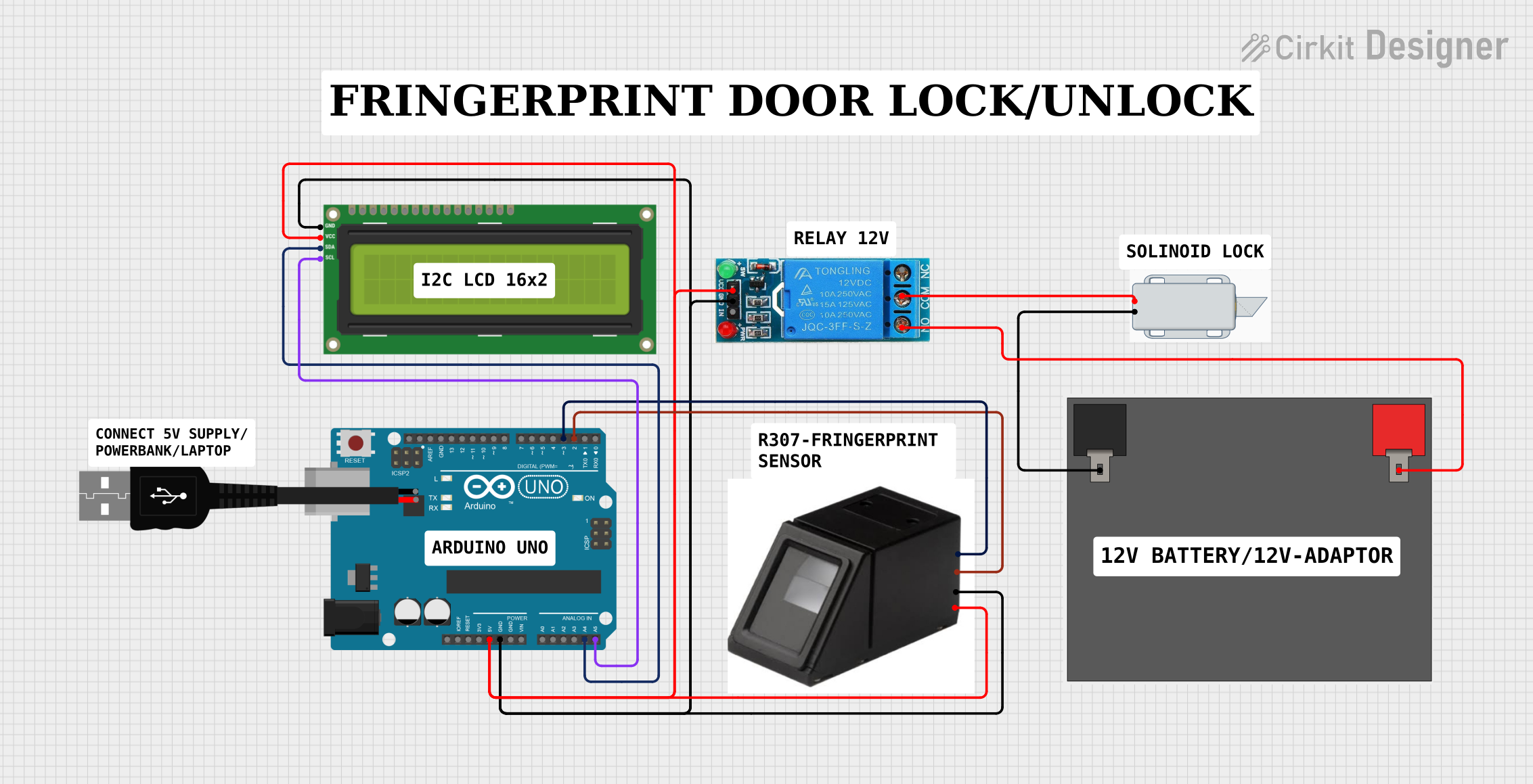
This circuit is designed to interface an Arduino UNO with a fingerprint sensor, an I2C LCD screen, a 12V solenoid lock, and a single-channel 12V relay. The Arduino UNO acts as the central controller, managing the input from the fingerprint sensor and outputting status information to the LCD screen. The relay is used to control the power to the solenoid lock, which acts as an electronic lock mechanism. The system is powered by a 12V 5Ah battery, which also supplies power to the relay and the solenoid lock.
Component List
Arduino UNO
- Microcontroller board based on the ATmega328P
- Provides digital and analog I/O pins
- Can be powered via USB or an external power supply
Fingerprint Sensor
- Biometric sensor for fingerprint detection and verification
- Interfaces with the Arduino via serial communication
I2C LCD 16x2 Screen
- Alphanumeric liquid crystal display
- Uses I2C communication for displaying text and numbers
- Requires 5V power supply
12V Single Channel Relay
- Electromechanical switch with one normally open (NO) contact
- Controlled by an input signal from the Arduino
- Used to switch the solenoid lock on and off
12V Solenoid Lock
- Electrically-controlled lock mechanism
- Operates on 12V power supply
12V 5Ah Battery
- Provides the main power supply for the circuit
- Powers the solenoid lock and the relay
USB Male 2 Pin Connection
- Used to provide power to the Arduino UNO from an external source
Wiring Details
Arduino UNO
5VandGNDpins are used to power the fingerprint sensor, relay, and LCD screen.A4 (SDA)andA5 (SCL)pins are connected to the corresponding SDA and SCL pins on the LCD screen for I2C communication.D2andD3pins are used for serial communication with the fingerprint sensor (D2connected to TX of the sensor,D3connected to RX of the sensor).
Fingerprint Sensor
- Powered by 5V and GND from the Arduino.
TXconnected toD2on the Arduino for serial communication.RXconnected toD3on the Arduino for serial communication.
I2C LCD 16x2 Screen
VCC (5V)andGNDconnected to the 5V and GND on the Arduino for power.SDAconnected toA4on the Arduino for I2C data.SCLconnected toA5on the Arduino for I2C clock.
12V Single Channel Relay
VCCconnected to 5V on the Arduino for power.GNDconnected to GND on the Arduino.COMconnected to the negative terminal of the solenoid lock.NOconnected to the positive terminal of the 12V battery.
12V Solenoid Lock
+connected to the positive terminal of the 12V battery through theNOcontact of the relay.-connected to theCOMcontact of the relay.
12V 5Ah Battery
12v +connected to theNOcontact of the relay and the positive terminal of the solenoid lock.12v -connected to theCOMcontact of the relay.
Documented Code
Arduino UNO Code (sketch.ino)
void setup() {
  // put your setup code here, to run once:

}

void loop() {
  // put your main code here, to run repeatedly:

}
Note: The provided code is a template and does not include specific functionality. It should be populated with the setup and loop routines required to control the fingerprint sensor, relay, and LCD screen.