
Circuit Documentation
Summary
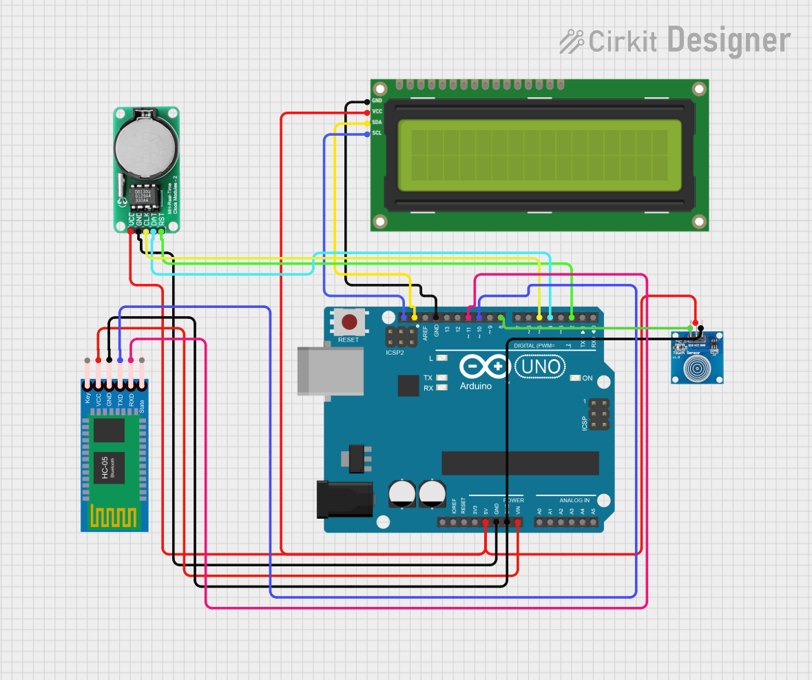
The circuit in question is designed to interface an Arduino UNO with several peripheral devices, including an I2C LCD 16x2 Screen, a DS1302 Real-Time Clock (RTC) module, a touch sensor, and an HC-05 Bluetooth Module. The Arduino UNO serves as the central microcontroller, managing communication and control between the connected devices. The circuit is powered through the Arduino's 5V and GND pins, with the HC-05 Bluetooth Module additionally connected to the Vin pin for power. Communication with the I2C LCD is achieved via the SCL and SDA pins, while the touch sensor and DS1302 RTC module are interfaced through specific digital I/O pins. The HC-05 Bluetooth Module is connected to the Arduino's serial communication pins for wireless data exchange.
Component List
Arduino UNO
- Microcontroller board based on the ATmega328P
- Provides digital and analog I/O pins
- Features serial communication capabilities
DS1302 RTC
- Real-Time Clock module for timekeeping
- Communicates with the microcontroller via a serial interface
Touch Sensor
- Capacitive touch sensor module
- Provides a digital output upon touch detection
HC-05 Bluetooth Module
- Wireless communication module using Bluetooth technology
- Facilitates serial communication with other Bluetooth-enabled devices
I2C LCD 16x2 Screen
- Liquid Crystal Display with 16 characters by 2 lines
- Uses I2C communication protocol for displaying text and characters
Wiring Details
Arduino UNO
- 5V: Powers the I2C LCD, DS1302 RTC, and touch sensor
- GND: Common ground for DS1302 RTC, HC-05 Bluetooth Module, touch sensor, and I2C LCD
- Vin: Powers the HC-05 Bluetooth Module
- SCL: Connected to the SCL pin of the I2C LCD for clock signal in I2C communication
- SDA: Connected to the SDA pin of the I2C LCD for data signal in I2C communication
- D11: Connected to the RXD pin of the HC-05 Bluetooth Module for serial communication
- D10: Connected to the TXD pin of the HC-05 Bluetooth Module for serial communication
- D8: Connected to the IO pin of the touch sensor for touch detection signal
- D5: Connected to the CLK pin of the DS1302 RTC for clock signal
- D4: Connected to the DATA pin of the DS1302 RTC for data exchange
- D2: Connected to the RST pin of the DS1302 RTC for reset signal
DS1302 RTC
- VCC: Powered by the 5V output from the Arduino UNO
- GND: Connected to the common ground on the Arduino UNO
- CLK: Receives clock signal from Arduino UNO's D5 pin
- DATA: Data exchange with Arduino UNO's D4 pin
- RST: Reset signal from Arduino UNO's D2 pin
Touch Sensor
- IO: Digital output connected to Arduino UNO's D8 pin
- VCC: Powered by the 5V output from the Arduino UNO
- GND: Connected to the common ground on the Arduino UNO
HC-05 Bluetooth Module
- Key: Not connected in this circuit
- VCC: Powered by the Vin output from the Arduino UNO
- TXD: Transmits data to Arduino UNO's D10 pin
- RXD: Receives data from Arduino UNO's D11 pin
- State: Not connected in this circuit
- GND: Connected to the common ground on the Arduino UNO
I2C LCD 16x2 Screen
- SCL: Clock signal from Arduino UNO's SCL pin
- SDA: Data signal from Arduino UNO's SDA pin
- VCC (5V): Powered by the 5V output from the Arduino UNO
- GND: Connected to the common ground on the Arduino UNO
Documented Code
Arduino UNO Code (sketch.ino)
void setup() {
  // put your setup code here, to run once:

}

void loop() {
  // put your main code here, to run repeatedly:

}
Note: The provided code is a template and does not include specific functionality. It should be populated with the setup and loop routines required to control the connected components and implement the desired behavior of the circuit.