
Arduino-Based Smart Home Automation System with LCD Display and Sensor Integration
View and Edit Project In Cirkit Designer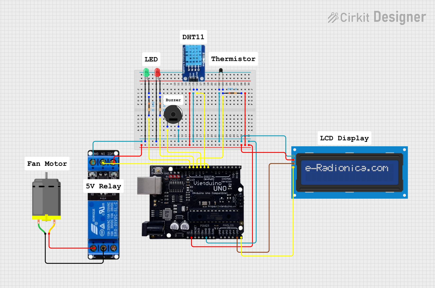
Circuit Documentation
Summary
This circuit involves a variety of components including LEDs, a piezo buzzer, an LCD screen, resistors, a microcontroller (Vietduino Uno), a temperature sensor (NTC), a humidity sensor (DHT11), a DC motor, and a relay. The circuit is designed to interface these components with the microcontroller to perform various functions such as displaying information on the LCD, controlling the motor, and reading sensor data.
Component List
LED: Two Pin (red)
- Pins: cathode, anode
- Description: A red LED used for visual indication.
LED: Two Pin (green)
- Pins: cathode, anode
- Description: A green LED used for visual indication.
Piezo Buzzer
- Pins: pin 1, pin 2
- Description: A piezoelectric buzzer used for sound output.
LCD screen 16x2 I2C
- Pins: SCL, SDA, VCC, GND
- Description: A 16x2 character LCD screen with I2C interface.
Resistor (200 Ohms)
- Pins: pin1, pin2
- Description: A resistor with a resistance of 200 Ohms.
Vietduino Uno USB-B
- Pins: AREF, GND, 13, 12, 11, 10, 9, 8, 7, 6, 5, 4, 3, 2, 1, 0, 3V3, 5V, RESET, VIN, A0, A1, A2, A3, A4, A5
- Description: A microcontroller board based on the Arduino Uno.
NTC
- Pins: A0, A1
- Description: A negative temperature coefficient thermistor used for temperature sensing.
DHT11
- Pins: DATA, GND, VCC
- Description: A digital temperature and humidity sensor.
DC Motor
- Pins: pin 1, pin 2
- Description: A DC motor used for mechanical movement.
Relay 12V
- Pins: ground, in, VCC, NO, COM, NC
- Description: A 12V relay used for switching high power devices.
Wiring Details
LED: Two Pin (red)
- cathode: Connected to the ground net.
- anode: Connected to pin1 of a 200 Ohm resistor.
LED: Two Pin (green)
- cathode: Connected to the ground net.
- anode: Connected to pin1 of a 200 Ohm resistor.
Piezo Buzzer
- pin 1: Connected to pin 10 of the Vietduino Uno.
- pin 2: Connected to the ground net.
LCD screen 16x2 I2C
- SCL: Connected to pin A5 of the Vietduino Uno.
- SDA: Connected to pin A4 of the Vietduino Uno.
- VCC: Connected to the 5V net.
- GND: Connected to the ground net.
Resistor (200 Ohms)
- pin1: Connected to the anode of the red LED.
- pin2: Connected to pin 13 of the Vietduino Uno.
Resistor (200 Ohms)
- pin1: Connected to the anode of the green LED.
- pin2: Connected to pin 12 of the Vietduino Uno.
Resistor (200 Ohms)
- pin1: Connected to pin A1 of the NTC.
- pin2: Connected to pin 11 of the Vietduino Uno.
Vietduino Uno USB-B
- GND: Connected to the ground net.
- 5V: Connected to the 5V net.
- 13: Connected to pin2 of a 200 Ohm resistor.
- 12: Connected to pin2 of a 200 Ohm resistor.
- 11: Connected to pin2 of a 200 Ohm resistor.
- 10: Connected to pin 1 of the Piezo Buzzer.
- 9: Connected to the DATA pin of the DHT11.
- 8: Connected to the in pin of the relay.
- A5: Connected to the SCL pin of the LCD screen.
- A4: Connected to the SDA pin of the LCD screen.
NTC
- A0: Connected to the ground net.
- A1: Connected to pin1 of a 200 Ohm resistor.
DHT11
- DATA: Connected to pin 9 of the Vietduino Uno.
- GND: Connected to the ground net.
- VCC: Connected to the 5V net.
DC Motor
- pin 1: Connected to the COM pin of the relay.
- pin 2: Connected to the NO pin of the relay.
Relay 12V
- ground: Connected to the ground net.
- in: Connected to pin 8 of the Vietduino Uno.
- VCC: Connected to the 5V net.
- NO: Connected to pin 2 of the DC Motor.
- COM: Connected to pin 1 of the DC Motor.
Code
No code is provided for this circuit.
This documentation provides a comprehensive overview of the circuit, including a detailed list of components and their wiring connections. This should help in understanding the circuit design and facilitate troubleshooting or modifications.