
Arduino Nano and nRF24L01 Wireless Controlled Robotic Platform
View and Edit Project In Cirkit Designer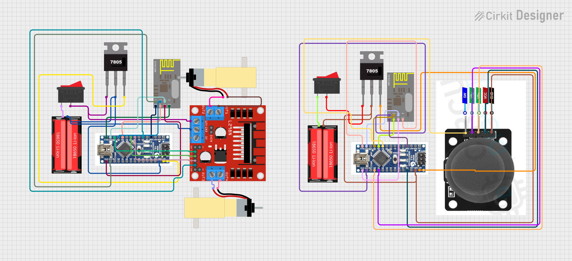
Circuit Documentation
Summary
This circuit is designed to control two hobby gearmotors using an L298N DC motor driver, which is interfaced with an Arduino Nano microcontroller. The system also includes wireless communication capabilities through the nRF24L01 modules, allowing for remote control. Power management is handled by 18650 Li-Ion batteries in conjunction with 7805 voltage regulators to provide a stable 5V supply to the Arduino Nanos and other 5V components. A joystick module is connected to one of the Arduino Nanos for manual control. Rocker switches are used to control the power flow from the batteries to the circuit.
Component List
Microcontrollers
- Arduino Nano: A compact microcontroller board based on the ATmega328P, featuring digital and analog I/O pins.
Communication Modules
- nRF24L01: A 2.4GHz wireless transceiver module for enabling wireless communication between devices.
Power Components
- 18650 Li-Ion Battery: A rechargeable lithium-ion battery providing the main power source for the circuit.
- 7805 Voltage Regulator: A voltage regulator that outputs a stable 5V from a higher voltage input.
Motor Driver
- L298N DC Motor Driver: A dual H-bridge motor driver capable of driving two DC motors or one stepper motor.
Motors
- Hobby Gearmotor with 48:1 Gearbox: A DC motor with an integrated gearbox for increased torque.
Switches
- Rocker Switch: A simple on-off switch to control the power supply to the circuit.
Sensors and Input Devices
- Joystick Module: An analog input device with a built-in switch, providing two-axis control and a pushbutton feature.
Wiring Details
Arduino Nano
- Digital Pins:
- D12: Connected to MISO of nRF24L01 for SPI communication.
- D11: Connected to MOSI of nRF24L01 for SPI communication.
- D10, D6, D5, D3: Connected to IN1, IN2, IN3, IN4 of L298N for motor control.
- D9: Connected to CSN of nRF24L01 for SPI communication.
- D8: Connected to CE of nRF24L01 to enable/disable the module.
- D7: Connected to SW of the Joystick Module (if present).
- D13: Connected to SCK of nRF24L01 for SPI communication.
- Analog Pins:
- A0: Connected to VRX of the Joystick Module for X-axis input (if present).
- A1: Connected to VRY of the Joystick Module for Y-axis input (if present).
- Power Pins:
- 3V3: Connected to VCC of nRF24L01 to power the module.
- 5V: Connected to VCC of the Joystick Module (if present).
- GND: Common ground with nRF24L01, L298N, Joystick Module, and 7805.
- VIN: Connected to Vout of 7805 to receive regulated 5V power.
nRF24L01
- Power Pins:
- VCC: Connected to 3V3 of Arduino Nano.
- GND: Common ground with Arduino Nano.
- SPI Pins:
- CE: Connected to D8 of Arduino Nano.
- CSN: Connected to D9 of Arduino Nano.
- SCK: Connected to D13 of Arduino Nano.
- MOSI: Connected to D11 of Arduino Nano.
- MISO: Connected to D12 of Arduino Nano.
Rocker Switch
- Pins:
- Pin 1: Connected to the Positive terminal of the 18650 Li-Ion battery.
- Pin 2: Connected to Vin of 7805 and 12V of L298N.
18650 Li-Ion Battery
- Pins:
- Positive: Connected to Pin 1 of Rocker Switch.
- Negative: Common ground with 7805, Arduino Nano, and L298N.
L298N DC Motor Driver
- Power Pins:
- 12V: Connected to Pin 2 of Rocker Switch.
- GND: Common ground with Arduino Nano, 7805, and 18650 Li-Ion battery.
- Motor Control Pins:
- IN1, IN2, IN3, IN4: Connected to D10, D6, D5, D3 of Arduino Nano respectively.
- Motor Output Pins:
- OUT1, OUT2: Connected to pins of one Hobby Gearmotor.
- OUT3, OUT4: Connected to pins of the other Hobby Gearmotor.
Hobby Gearmotor with 48:1 Gearbox
- Pins:
- Pin 1: Connected to OUT2 or OUT4 of L298N.
- Pin 2: Connected to OUT1 or OUT3 of L298N.
7805 Voltage Regulator
- Pins:
- Vin: Connected to Pin 2 of Rocker Switch and Positive terminal of 18650 Li-Ion battery.
- Gnd: Common ground with Arduino Nano, L298N, and 18650 Li-Ion battery.
- Vout: Connected to VIN of Arduino Nano.
Joystick Module (if present)
- Pins:
- SW: Connected to D7 of Arduino Nano.
- VRX: Connected to A0 of Arduino Nano.
- VRY: Connected to A1 of Arduino Nano.
- VCC: Connected to 5V of Arduino Nano.
- GND: Common ground with Arduino Nano, 18650 Li-Ion battery, and 7805.
Documented Code
No code has been provided for the microcontrollers in this circuit. The code would typically include initialization of the SPI interface for communication with the nRF24L01 modules, setup of the digital I/O pins for motor control via the L298N driver, and analog input reading for the joystick module. Additionally, the code would handle the wireless communication protocol to receive commands for the motors and send back any necessary feedback.