Arduino Mega 2560 Controlled LCD Display with Adjustable Contrast
Circuit Documentation
Summary
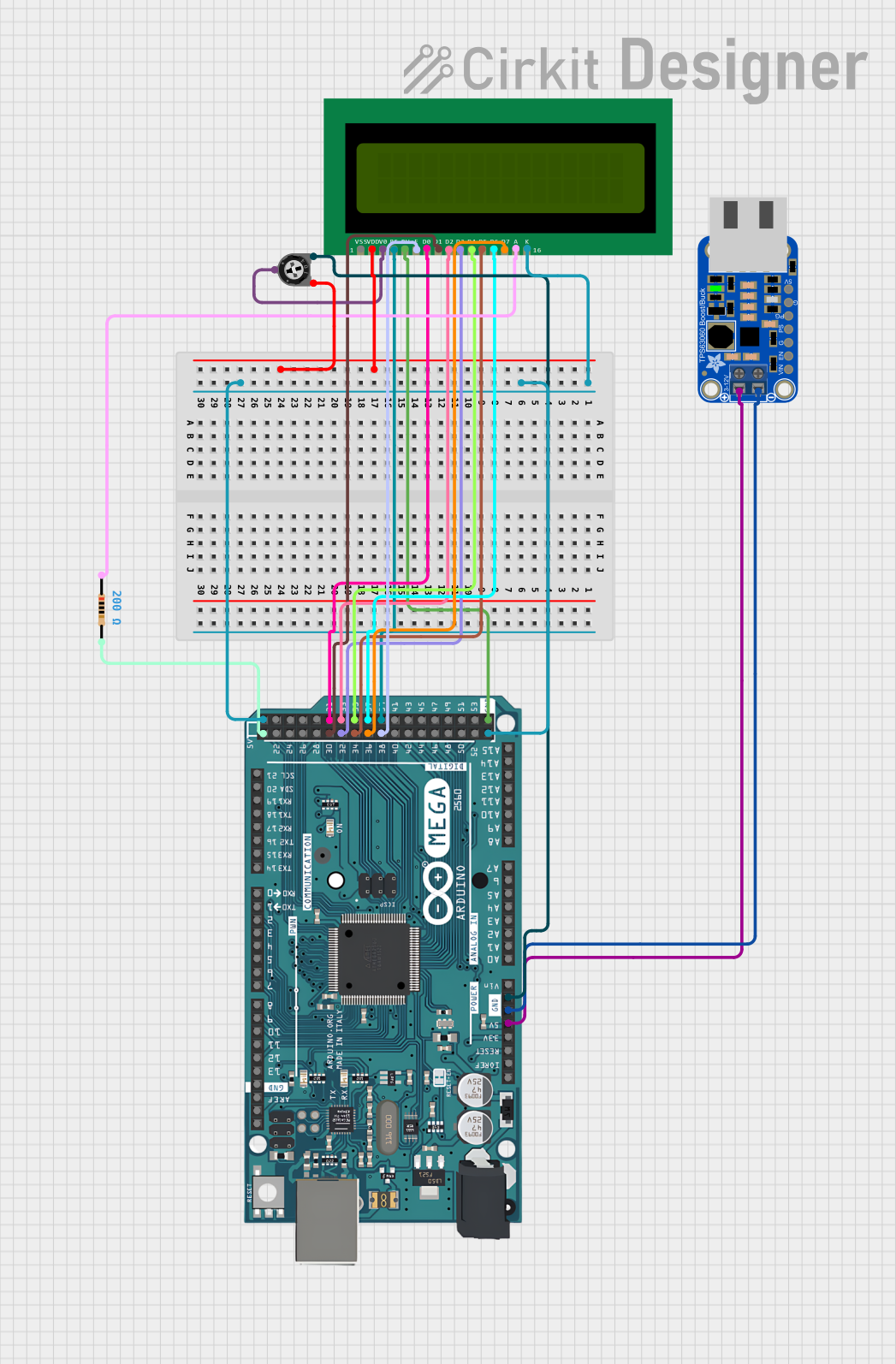
This document describes a circuit that interfaces a 16x2 LCD with an Arduino Mega 2560 microcontroller. The circuit includes a voltage regulator module (verter_usb), a trimmer potentiometer for adjusting the LCD contrast, and a resistor for backlight control. The Arduino Mega 2560 controls the LCD, displaying a simple message. The voltage regulator provides a stable 5V supply to the Arduino, which in turn powers the LCD. The ground connections are shared among the components to complete the circuit.
Component List
Verter USB
- Pins: VIN, ENABLE, GND, PS, PG, 5.0V
- Description: A voltage regulator module used to provide a stable 5V power supply.
Arduino Mega 2560
- Pins: IOREF, RESET, 3V3, 5V, GND, VIN, Digital, Analog, Communication, PWM, and other control pins.
- Description: A microcontroller board based on the ATmega2560, with numerous digital and analog I/O pins.
16X2 LCD
- Pins: VSS, VDD, V0, RS, RW, E, D0-D7, A, K
- Description: A liquid crystal display capable of displaying two lines of 16 characters each.
Resistor
- Pins: pin1, pin2
- Value: 200 Ohms
- Description: A resistor used to limit current, possibly for the LCD backlight.
Trimmer Potentiometer
- Pins: leg1, wiper, leg2
- Value: 10,000 Ohms
- Description: A variable resistor used to adjust the contrast of the LCD.
Wiring Details
Verter USB
- VIN connected to Arduino Mega 2560 5V
- GND connected to Arduino Mega 2560 GND
Arduino Mega 2560
- 5V connected to Verter USB VIN and Resistor pin2
- GND connected to Verter USB GND, Trimmer Potentiometer leg2, 16X2 LCD RW, and 16X2 LCD K
- Digital Pins connected to 16X2 LCD control and data pins:
- D38 to LCD E
- D39 to LCD RS
- D30-D37 to LCD D0-D7
16X2 LCD
- VSS connected to Arduino Mega 2560 GND
- VDD connected to Trimmer Potentiometer leg1
- V0 connected to Trimmer Potentiometer wiper
- A connected to Resistor pin1
- K connected to Arduino Mega 2560 GND
- Control and Data Pins connected to corresponding Arduino Mega 2560 digital pins
Resistor
- pin1 connected to 16X2 LCD A
- pin2 connected to Arduino Mega 2560 5V
Trimmer Potentiometer
- leg1 connected to 16X2 LCD VDD
- wiper connected to 16X2 LCD V0
- leg2 connected to Arduino Mega 2560 GND
Documented Code
/*
 * This Arduino sketch interfaces a 16x2 LCD with an Arduino Mega 2560.
 * The LCD is connected to various digital pins of the Arduino.
 * A trimmer potentiometer is used to adjust the contrast of the LCD.
 * The code initializes the LCD and displays a simple message.
 */

#include <LiquidCrystal.h>

// Initialize the library with the numbers of the interface pins
LiquidCrystal lcd(39, 38, 31, 30, 33, 32, 35, 34, 37, 36);

void setup() {
  // Set up the LCD's number of columns and rows:
  lcd.begin(16, 2);
  // Print a message to the LCD.
  lcd.print("Hello, World!");
}

void loop() {
  // Nothing to do here
}
This code initializes the 16x2 LCD and displays the message "Hello, World!" on it. The LiquidCrystal library is used to manage the communication between the Arduino and the LCD. The lcd object is created with the pin numbers corresponding to the RS, E, and data pins D0-D7. The setup function initializes the LCD's size and prints the initial message. The loop function is empty as no dynamic behavior is required.