
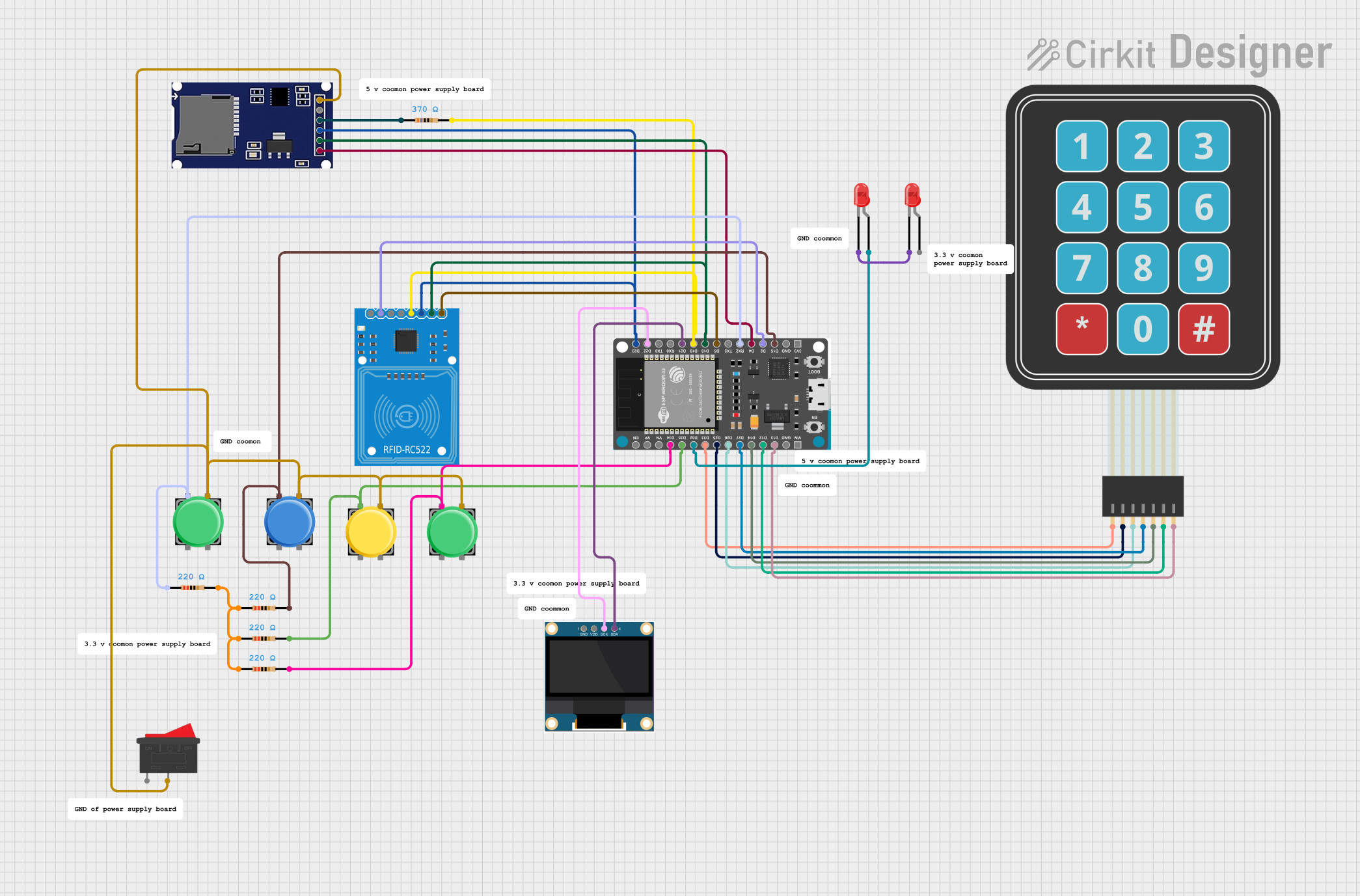
Circuit Documentation
Summary
This circuit is designed to interface an ESP32 microcontroller with various input and output devices, including a membrane matrix keypad, pushbuttons, LEDs, an RFID reader, an SD card module, and an OLED display. The circuit is capable of reading RFID tags, logging data to an SD card, displaying information on an OLED screen, and handling user input through a keypad and pushbuttons. The ESP32 also connects to Wi-Fi for data uploading.
Component List
Membrane Matrix Keypad
- Pins: Row 1, Row 2, Row 3, Row 4, Column 1, Column 2, Column 3
- Description: A 4x3 matrix keypad used for user input.
Pushbutton
- Pins: Pin 1, Pin 2, Pin 3, Pin 4
- Description: A simple pushbutton used for user input.
LED: Two Pin (red)
- Pins: Cathode, Anode
- Description: A red LED used for visual indication.
Resistor
- Pins: Pin 1, Pin 2
- Description: A resistor with a resistance of 220 Ohms.
RFID-RC522
- Pins: SDA, SCK, MOSI, MISO, IRQ, GND, RST, 3.3V
- Description: An RFID reader module used for reading RFID tags.
ESP32 Devkit V1
- Pins: 3V3, GND, D15, D2, D4, RX2, TX2, D5, D18, D19, D21, RX0, TX0, D22, D23, EN, VP, VN, D34, D35, D32, D33, D25, D26, D27, D14, D12, D13, VIN
- Description: A development board for the ESP32 microcontroller.
SD Module
- Pins: CS, SCK, MOSI, MISO, VCC, GND
- Description: An SD card module used for data storage.
Rocker Switch
- Pins: 1, 2
- Description: A simple on/off switch.
0.96" OLED
- Pins: GND, VDD, SCK, SDA
- Description: A small OLED display used for visual output.
Wiring Details
Membrane Matrix Keypad
- Row 1: Connected to ESP32 pin D33
- Row 2: Connected to ESP32 pin D25
- Row 3: Connected to ESP32 pin D26
- Row 4: Connected to ESP32 pin D27
- Column 1: Connected to ESP32 pin D14
- Column 2: Connected to ESP32 pin D12
- Column 3: Connected to ESP32 pin D13
Pushbutton 1
- Pin 1: Connected to ESP32 pin D15 and Resistor pin2
- Pin 2: Not connected
- Pin 3: Connected to GND
- Pin 4: Not connected
Pushbutton 2
- Pin 1: Connected to ESP32 pin RX2 and Resistor pin1
- Pin 2: Not connected
- Pin 3: Connected to GND
- Pin 4: Not connected
Pushbutton 3
- Pin 1: Connected to ESP32 pin D34 and Resistor pin2
- Pin 2: Not connected
- Pin 3: Connected to GND
- Pin 4: Not connected
Pushbutton 4
- Pin 1: Connected to ESP32 pin D35 and Resistor pin2
- Pin 2: Not connected
- Pin 3: Connected to GND
- Pin 4: Not connected
LED: Two Pin (red) 1
- Anode: Connected to ESP32 pin D32
- Cathode: Connected to GND
LED: Two Pin (red) 2
- Anode: Not connected
- Cathode: Connected to GND
Resistor 1
- Pin 1: Connected to ESP32 pin RX2
- Pin 2: Connected to Pushbutton 2 pin1
Resistor 2
- Pin 1: Connected to ESP32 pin D34
- Pin 2: Connected to Pushbutton 3 pin1
Resistor 3
- Pin 1: Connected to ESP32 pin D35
- Pin 2: Connected to Pushbutton 4 pin1
Resistor 4
- Pin 1: Connected to ESP32 pin D15
- Pin 2: Connected to Pushbutton 1 pin1
Resistor 5
- Pin 1: Connected to SD Module pin MISO
- Pin 2: Connected to ESP32 pin D19
RFID-RC522
- SDA: Connected to ESP32 pin D5
- SCK: Connected to ESP32 pin D18
- MOSI: Connected to ESP32 pin D23
- MISO: Connected to ESP32 pin D19
- IRQ: Not connected
- GND: Connected to GND
- RST: Connected to ESP32 pin D2
- 3.3V: Connected to 3.3V
SD Module
- CS: Connected to ESP32 pin D4
- SCK: Connected to ESP32 pin D18
- MOSI: Connected to ESP32 pin D23
- MISO: Connected to Resistor pin1
- VCC: Connected to 3.3V
- GND: Connected to GND
Rocker Switch
- Pin 1: Not connected
- Pin 2: Connected to GND
0.96" OLED
- GND: Connected to GND
- VDD: Connected to 3.3V
- SCK: Connected to ESP32 pin D22
- SDA: Connected to ESP32 pin D21
Documented Code
#include <Arduino.h>
#include <Wire.h>
#include <Adafruit_GFX.h>
#include <Adafruit_SSD1306.h>
#include <HTTPClient.h>
#include "FS.h"
#include "SD.h"
#include <SPI.h>
#include <MFRC522.h>
#include <WiFi.h>
#include <WiFiUdp.h>
#include <time.h>
#include <sntp.h>
#include <Wire.h>
#include <Adafruit_GFX.h>
#include <ArduinoJson.h>  // Include the ArduinoJson library
#include <Keypad.h>

// Length of password + 1 for null character
#define Password_Length 8

// Character to hold password input
char Data[Password_Length];
// Password

// Counter for character entries
byte data_count = 0;

// Character to hold key input
char customKey;

// Constants for row and column sizes
const byte ROWS = 4;
const byte COLS = 3;

// Array to represent keys on keypad
char hexaKeys[ROWS][COLS] = {
  {'1', '2', '3'},
  {'4', '5', '6'},
  {'7', '8', '9'},
  {'*', '0', '#'}
};

// Connections to Arduino
byte rowPins[ROWS] = {33, 25, 26, 27}; //connect to the row pinouts of the keypad
byte colPins[COLS] = {14, 12, 13}; //connect to the column pinouts of the keypad

// Create keypad object
Keypad customKeypad = Keypad(makeKeymap(hexaKeys), rowPins, colPins, ROWS, COLS);

#define SS_PIN  5    // SDA pin esp32=5
#define RST_PIN 2   // RST pin  esp32=22
#define SD_CS 4      // CS pin for SD card
#define Wifi_LED 32

#define SCREEN_WIDTH 128 // OLED display width, in pixels
#define SCREEN_HEIGHT 64 // OLED display height, in pixels

// Declaration for SSD1306 display connected using I2C
#define OLED_RESET     -1 // Reset pin # (or -1 if sharing Arduino reset pin)
Adafruit_SSD1306 display(SCREEN_WIDTH, SCREEN_HEIGHT, &Wire, OLED_RESET);

const int buttonPin = 15;           // GPIO pin for the push button
int counter = 0;                    // Counter variable
int lastButtonState = HIGH;         // Last button state (HIGH because of pull-up)
int buttonState;                    // Current button state
unsigned long lastDebounceTime = 0; // Last time