
Circuit Documentation
Summary of the Circuit
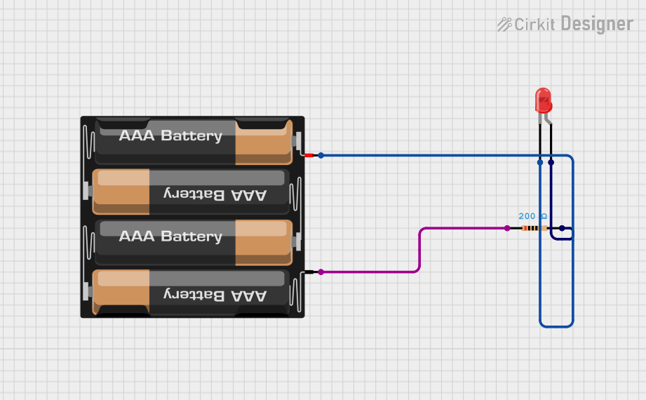
This circuit is a simple LED circuit powered by a 4 x AAA battery mount. It consists of a red two-pin LED, a resistor, and a battery mount for power supply. The LED is connected in series with the resistor to limit the current flowing through the LED, thus protecting it from damage due to overcurrent. The battery mount provides the necessary voltage to power the LED. There is no microcontroller or embedded code associated with this circuit.
Component List
LED: Two Pin (red)
- Description: A basic red LED used for indicating power or status.
- Pins:
- Cathode: The negative pin of the LED.
- Anode: The positive pin of the LED.
Resistor
- Description: A resistor used to limit the current through the LED.
- Pins:
- Pin1
- Pin2
- Properties:
- Resistance: 200 Ohms
4 x AAA Battery Mount
- Description: A battery mount for holding four AAA batteries to provide power to the circuit.
- Pins:
- Positive (+): The positive terminal of the battery mount.
- Negative (-): The negative terminal of the battery mount.
Wiring Details
LED: Two Pin (red)
- Cathode: Connected to the positive (+) terminal of the 4 x AAA Battery Mount.
- Anode: Connected to Pin2 of the Resistor.
Resistor
- Pin1: Connected to the negative (-) terminal of the 4 x AAA Battery Mount.
- Pin2: Connected to the Anode of the LED: Two Pin (red).
4 x AAA Battery Mount
- Positive (+): Connected to the Cathode of the LED: Two Pin (red).
- Negative (-): Connected to Pin1 of the Resistor.
Documented Code
There is no microcontroller or embedded code associated with this circuit.