
ESP8266 NodeMCU-Based Environmental Monitoring and Health Tracking System with Wi-Fi Connectivity
View and Edit Project In Cirkit Designer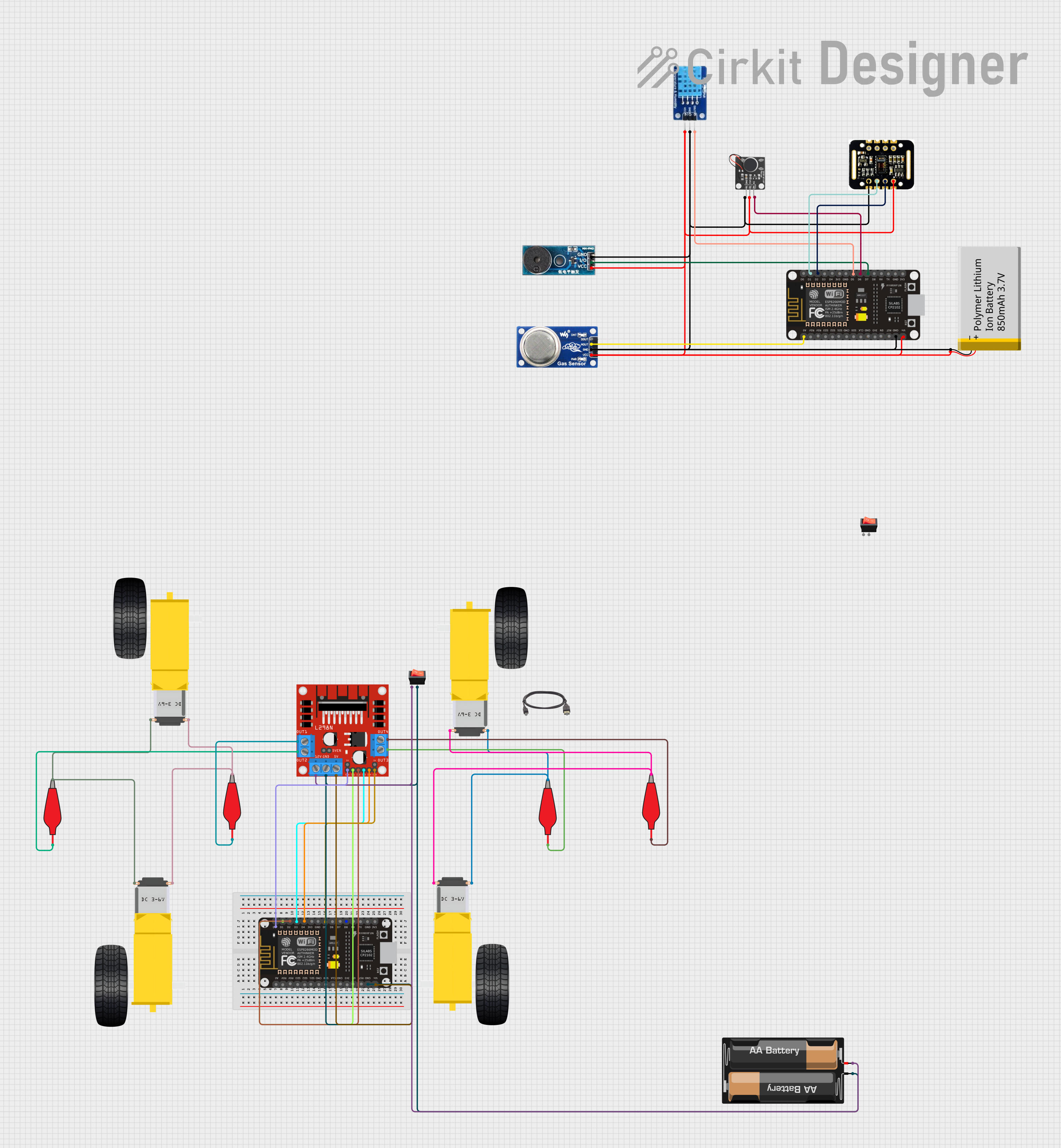
Circuit Documentation
Summary
The circuit in question is designed to monitor environmental parameters such as temperature, humidity, gas levels, and also includes health monitoring features like heart rate and blood oxygen saturation (SpO2) measurement. It utilizes an ESP8266 NodeMCU as the central microcontroller unit, interfaced with various sensors including a DHT11 for temperature and humidity, an MQ6 gas sensor, a MAX30102 sensor for heart rate and SpO2, and additional components like a buzzer, a vibration motor, and motor drivers for actuation purposes. The circuit is powered by a Polymer Lithium Ion Battery and includes a motor driver to control DC motors, presumably for a mobile platform.
Component List
- ESP8266 NodeMCU: A Wi-Fi enabled microcontroller board based on the ESP8266 chip, featuring digital and analog pins, power pins, and serial communication capabilities.
- DHT11: A basic, low-cost digital temperature and humidity sensor.
- MQ6: A gas sensor designed for detecting LPG, butane, propane, methane, alcohol, hydrogen, and smoke.
- Buzzer Module: An electronic buzzer for audible alerts.
- PWM Vibration Motor Sensor Module Switch: A module that controls a vibration motor, typically used for haptic feedback.
- MAX30102 HR + SpO2 Sensor: An integrated pulse oximetry and heart-rate monitor sensor module.
- Polymer Lithium Ion Battery - 850mAh: A rechargeable battery providing power to the circuit.
- L298N DC Motor Driver: A high-power motor driver module capable of driving up to two DC motors.
- Gearmotor DC Wheels: DC motors with gearboxes attached, used for driving wheels.
- 2 x AA Battery Mount: A battery holder for two AA batteries.
- Alligator Clip Cable: Cables with alligator clips used for making temporary electrical connections.
- Rocker Switch: A switch to control the power supply to the circuit.
- Type-B to USB Cable: A cable for connecting USB devices with a Type-B connector.
Wiring Details
ESP8266 NodeMCU
- D1: Connected to SCL pin of MAX30102 sensor.
- D2: Connected to SDA pin of MAX30102 sensor.
- D5: Connected to DATA pin of DHT11 sensor.
- D6: Connected to Signal pin of PWM Vibration Motor Sensor Module Switch.
- D7: Connected to I/O pin of Buzzer Module.
- A0: Connected to A0 pin of MQ6 gas sensor.
- GND: Common ground with MAX30102, DHT11, MQ6, PWM Vibration Motor Sensor Module Switch, Buzzer Module, Polymer Lithium Ion Battery, and L298N DC Motor Driver.
- VIN: Power input connected to VIN pin of MAX30102, VCC pin of DHT11, VCC pin of MQ6, Vcc pin of PWM Vibration Motor Sensor Module Switch, Vcc pin of Buzzer Module, and VCC pin of Polymer Lithium Ion Battery.
MAX30102 HR + SpO2 Sensor
- SCL: Connected to D1 pin of ESP8266 NodeMCU.
- SDA: Connected to D2 pin of ESP8266 NodeMCU.
- GND: Common ground.
- VIN: Power input from ESP8266 NodeMCU.
DHT11
- DATA: Connected to D5 pin of ESP8266 NodeMCU.
- GND: Common ground.
- VCC: Power input from ESP8266 NodeMCU.
MQ6 Gas Sensor
- A0: Connected to A0 pin of ESP8266 NodeMCU.
- GND: Common ground.
- VCC: Power input from ESP8266 NodeMCU.
Buzzer Module
- I/O: Connected to D7 pin of ESP8266 NodeMCU.
- GND: Common ground.
- Vcc: Power input from ESP8266 NodeMCU.
PWM Vibration Motor Sensor Module Switch
- Signal: Connected to D6 pin of ESP8266 NodeMCU.
- Ground: Common ground.
- Vcc: Power input from ESP8266 NodeMCU.
Polymer Lithium Ion Battery - 850mAh
- GND: Common ground.
- VCC: Power input to ESP8266 NodeMCU and other components.
L298N DC Motor Driver
- IN1, IN2, IN3, IN4: Control inputs from ESP8266 NodeMCU.
- ENA, ENB: Enable pins controlled by ESP8266 NodeMCU.
- OUT1, OUT2, OUT3, OUT4: Outputs connected to Gearmotor DC Wheels via Alligator Clip Cables.
- GND: Common ground.
- 5V: Power input from ESP8266 NodeMCU.
- 12V: Power input from 2 x AA Battery Mount through Rocker Switch.
Gearmotor DC Wheels
- PIN1, PIN2: Connected to outputs of L298N DC Motor Driver via Alligator Clip Cables.
2 x AA Battery Mount
- -: Ground connected to Rocker Switch and L298N DC Motor Driver.
- +: Positive terminal connected to Rocker Switch and L298N DC Motor Driver.
Alligator Clip Cables
- Pin: Connected to outputs of L298N DC Motor Driver.
- Alligator: Connected to pins of Gearmotor DC Wheels.
Rocker Switch
- Output: Connected to GND of ESP8266 NodeMCU and L298N DC Motor Driver.
- Input: Connected to positive terminal of 2 x AA Battery Mount and 12V input of L298N DC Motor Driver.
Documented Code
Main Sketch (sketch.ino)
#define BLYNK_TEMPLATE_ID "TMPL308E2KguH"
#define BLYNK_TEMPLATE_NAME "Tempruture and Humidity"
#define BLYNK_AUTH_TOKEN "Lt4kGTEKtDbmMKvszIJ2ACijS7lG3LpN"

#define BLYNK_PRINT Serial
#include <DHT.h>
#include <Wire.h>
#include <Blynk.h>
#include <ESP8266WiFi.h>
#include <BlynkSimpleEsp8266.h>

#include <MAX3010x.h>
#include "filters.h"

char auth[] = BLYNK_AUTH_TOKEN;
char ssid[] = "Ananda"; // Change your Wifi/ Hotspot Name
char pass[] = "123456789"; // Change your Wifi/ Hotspot Password

BlynkTimer timer;

#define DHTPIN D5          // What digital pin we're connected to
// Uncomment whatever type you're using!
#define DHTTYPE DHT11     // DHT 11
//#define DHTTYPE DHT22   // DHT 22, AM2302, AM2321
//#define DHTTYPE DHT21   // DHT 21, AM2301

int motorPin = D6; // vibration Motor
DHT dht(DHTPIN, DHTTYPE); //dht11 Sensor
// You should get Auth Token in the Blynk App.
// Go to the Project Settings (nut icon).

#define MQ5 A0
#define buzzer  D7
int MQ5_Val = 0;

WidgetLED led(V8);

// Sensor (adjust to your sensor type)
MAX30102 sensor;
const auto kSamplingRate = sensor.SAMPLING_RATE_400SPS;
const float kSamplingFrequency = 400.0;

// Finger Detection Threshold and Cooldown
const unsigned long kFingerThreshold = 10000;
const unsigned int kFingerCooldownMs = 500;

// Edge Detection Threshold (decrease for MAX30100)
const float kEdgeThreshold = -2000.0;

// Filters
const float kLowPassCutoff = 5.0;
const float kHighPassCutoff = 0.5;

// Averaging
const bool kEnableAveraging = false;
const int kAveragingSamples = 5;
const int kSampleThreshold = 5;

void setup()
{
  // Debug console
  Serial.begin(9600);

  Blynk.begin(auth, ssid, pass);
  // You can also specify server:
  //Blynk.begin(auth, ssid, pass, "blynk-cloud.com", 80);
  //Blynk.begin(auth, ssid, pass, IPAddress(192,168,1,100), 8080);

  pinMode(motorPin, OUTPUT );
  pinMode(buzzer, OUTPUT);

  if(sensor.begin() && sensor.setSamplingRate(kSamplingRate)) {
    Serial.println("Sensor initialized");
  }
  else {
    Serial.println("Sensor not found");
    while(1);
  }


  dht.begin();

  // Setup a function to be called every second
  timer.setInterval(1000L, sendSensor);
  delay(2000);
  timer.setInterval(1000L, mySensor);
}

// Filter Instances
LowPassFilter low_pass_filter_red(kLowPassCutoff, kSamplingFrequency);
LowPassFilter low_pass_filter_ir(kLowPassCutoff, kSamplingFrequency);
HighPassFilter high_pass_filter(kHighPassCutoff, kSamplingFrequency);
Differentiator differentiator(kSamplingFrequency);
MovingAverageFilter<kAveragingSamples> averager_b