
Arduino Nano Controlled Multi-Sensor Distance Measurement System with Ambient Light Sensing and Indicator LEDs
View and Edit Project In Cirkit Designer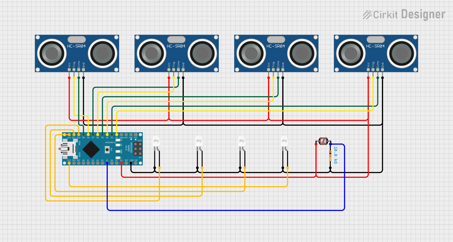
Circuit Documentation
Summary
This circuit is designed to interface multiple HC-SR04 Ultrasonic Sensors with an Arduino Nano microcontroller. The circuit also includes several LEDs and a photocell (LDR) connected to the Arduino. The ultrasonic sensors are used for distance measurement, while the LEDs serve as indicators, and the photocell is used for light sensing. The Arduino Nano controls the sensors and LEDs and processes the photocell's signal.
Component List
HC-SR04 Ultrasonic Sensor
- Description: An ultrasonic distance sensor that uses sonar to determine the distance to an object.
- Pins: VCC, TRIG, ECHO, GND
LED: Two Pin (white)
- Description: A white light-emitting diode used as an indicator.
- Pins: cathode, anode
Photocell (LDR)
- Description: A light-dependent resistor whose resistance varies with the intensity of light.
- Pins: pin 0, pin 1
Arduino Nano
- Description: A small, complete, and breadboard-friendly board based on the ATmega328 (Arduino Nano 3.x).
- Pins: D1/TX, D0/RX, RESET, GND, D2 to D13, VIN, 5V, A0 to A7, AREF, 3V3
Resistor
- Description: A passive two-terminal electrical component that implements electrical resistance as a circuit element.
- Resistance: 10000 Ohms
Wiring Details
HC-SR04 Ultrasonic Sensors
- VCC connected to Arduino Nano 5V
- GND connected to Arduino Nano GND
- TRIG and ECHO pins connected to various digital pins on the Arduino Nano
LEDs: Two Pin (white)
- cathode connected to Arduino Nano GND
- anode connected to various digital pins on the Arduino Nano
Photocell (LDR)
- pin 0 connected to Arduino Nano 5V
- pin 1 connected to Arduino Nano A5 through a 10k Ohm resistor to GND
Arduino Nano
- 5V and GND used to power the circuit
- Digital and analog pins used to interface with sensors and LEDs
Resistor
- One end connected to Arduino Nano A5
- The other end connected to GND and Photocell pin 1
Documented Code
void setup() {
  // put your setup code here, to run once:

}

void loop() {
  // put your main code here, to run repeatedly:

}
File: sketch.ino
Note: The provided code is a template and does not contain any functional code for operating the circuit. The user must implement the setup and loop functions to initialize the pins and define the circuit's behavior during operation.