
Piezo Sensor-Based LED Indicator with Rectifier and Pushbutton Control
View and Edit Project In Cirkit Designer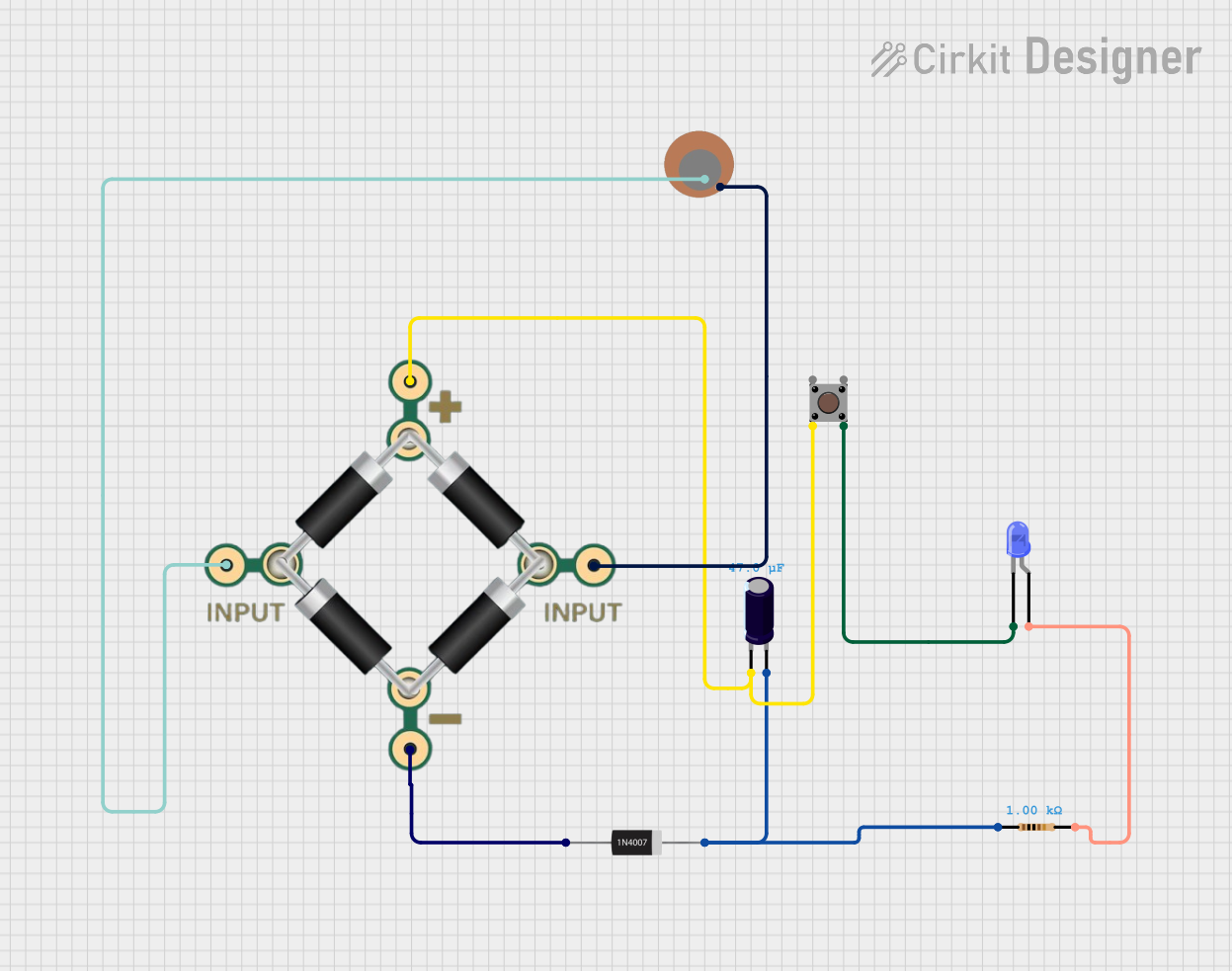
Circuit Documentation
Summary
This document provides a detailed description of a circuit that includes a piezo sensor, a bridge rectifier, a pushbutton, an electrolytic capacitor, a rectifier diode, a resistor, and an LED. The circuit is designed to convert the AC signal from the piezo sensor to a DC signal, which is then used to control an LED through a pushbutton.
Component List
1N4007 Rectifier Diode
- Pins: Cathode, Anode
- Description: A general-purpose rectifier diode used for converting AC to DC.
Electrolytic Capacitor
- Pins: -, +
- Description: A capacitor used for smoothing the rectified DC signal.
- Properties:
- Capacitance: 47 µF
BRIDGE - 1N4007
- Pins: 1 INPUT, 2 INPUT, + PIN, - PIN
- Description: A bridge rectifier made of 1N4007 diodes for converting AC to DC.
Pushbutton
- Pins: Pin 1 (in), Pin 2 (in), Pin 3 (out), Pin 4 (out)
- Description: A pushbutton switch used to control the LED.
LED: Two Pin (blue)
- Pins: Cathode, Anode
- Description: A blue LED used as an indicator.
Resistor
- Pins: pin1, pin2
- Description: A resistor used to limit the current through the LED.
- Properties:
- Resistance: 1000 Ohms
Piezo Sensor
- Pins: +, -
- Description: A piezoelectric sensor used to generate an AC signal.
Wiring Details
1N4007 Rectifier Diode
- Anode is connected to the - PIN of the BRIDGE - 1N4007.
- Cathode is connected to the + pin of the Electrolytic Capacitor and pin1 of the Resistor.
Electrolytic Capacitor
- - pin is connected to Pin 2 (in) of the Pushbutton and + PIN of the BRIDGE - 1N4007.
- + pin is connected to the Cathode of the 1N4007 Rectifier Diode and pin1 of the Resistor.
BRIDGE - 1N4007
- 1 INPUT is connected to the + pin of the Piezo Sensor.
- 2 INPUT is connected to the - pin of the Piezo Sensor.
- + PIN is connected to the - pin of the Electrolytic Capacitor and Pin 2 (in) of the Pushbutton.
- - PIN is connected to the Anode of the 1N4007 Rectifier Diode.
Pushbutton
- Pin 1 (in) is not connected.
- Pin 2 (in) is connected to the - pin of the Electrolytic Capacitor and + PIN of the BRIDGE - 1N4007.
- Pin 3 (out) is not connected.
- Pin 4 (out) is connected to the Cathode of the LED: Two Pin (blue).
LED: Two Pin (blue)
- Cathode is connected to Pin 4 (out) of the Pushbutton.
- Anode is connected to pin2 of the Resistor.
Resistor
- pin1 is connected to the + pin of the Electrolytic Capacitor and Cathode of the 1N4007 Rectifier Diode.
- pin2 is connected to the Anode of the LED: Two Pin (blue).
Piezo Sensor
- + pin is connected to 1 INPUT of the BRIDGE - 1N4007.
- - pin is connected to 2 INPUT of the BRIDGE - 1N4007.
Code
There is no microcontroller code associated with this circuit.