
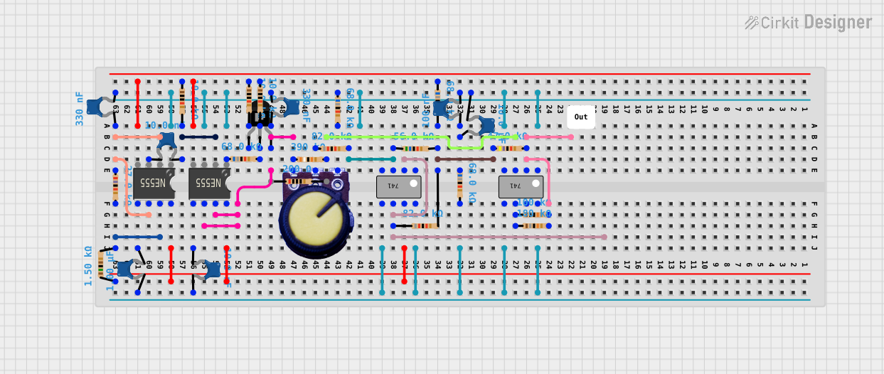
Circuit Documentation
Summary
This document provides a detailed overview of a complex electronic circuit. The circuit incorporates a variety of components including 555 Timer ICs, operational amplifiers (741 ICs), resistors, capacitors, a potentiometer, and a PNP transistor. The circuit's functionality is not explicitly stated, but it appears to be designed for signal processing or timing applications, given the use of 555 timers and operational amplifiers.
Component List
Integrated Circuits
- 555 Timer IC: A highly stable device for generating accurate time delays or oscillation.
- 741 IC (Operational Amplifier): A general-purpose operational amplifier with offset null capability.
Passive Components
- Resistors: Various resistors with different resistance values ranging from 200 Ohms to 390,000 Ohms.
- Ceramic Capacitors: Capacitors with capacitance values ranging from 10 pF to 1 µF.
- Potentiometer: A three-terminal resistor with an adjustable center tap, providing variable resistance.
Transistors
- PNP Transistor (EBC): A type of bipolar junction transistor with emitter, base, and collector pins.
Miscellaneous
- Comment: A placeholder for additional notes or comments about the circuit.
Wiring Details
555 Timer IC
- VCC+: Connected to the positive supply voltage.
- Dis: Discharge pin connected to various resistors and capacitors.
- Th: Threshold pin connected to resistors and capacitors.
- CV: Control voltage pin connected to capacitors.
- Rst: Reset pin (not detailed in the net list).
- Out: Output pin (not detailed in the net list).
- Trig: Trigger pin (not detailed in the net list).
- GND: Ground pin (not detailed in the net list).
741 IC (Operational Amplifier)
- Offset Null: Connected to capacitors and resistors for offset nulling.
- Inverting Input: Connected to the output and resistors for feedback.
- Non-Inverting Input: Connected to resistors.
- V-: Connected to resistors and capacitors.
- NC: No connection (not detailed in the net list).
- V+: Connected to the positive supply voltage.
- Output: Connected to resistors.
Resistors
- Various resistors are used throughout the circuit, connected between ICs, transistors, and other resistors.
Ceramic Capacitors
- Capacitors are connected to ICs and resistors, providing stability and filtering.
Potentiometer
- GND: Ground terminal.
- Output: Connected to a resistor.
- VCC: Connected to the positive supply voltage.
PNP Transistor (EBC)
- Emitter: Connected to a resistor.
- Base: Connected to resistors.
- Collector: Connected to the potentiometer, capacitors, and a 555 Timer IC.
Documented Code
No code has been provided for any microcontrollers in the circuit. If code becomes available, it should be documented in this section with appropriate comments and explanations for each function and routine.
This document serves as a basic framework for understanding the circuit's components and their interconnections. Further details, such as the specific values of the components and the overall purpose of the circuit, would be necessary for a complete understanding and analysis.