
Arduino-Controlled OLED Display and DC Motor with Relay and BTS7960 Driver
View and Edit Project In Cirkit Designer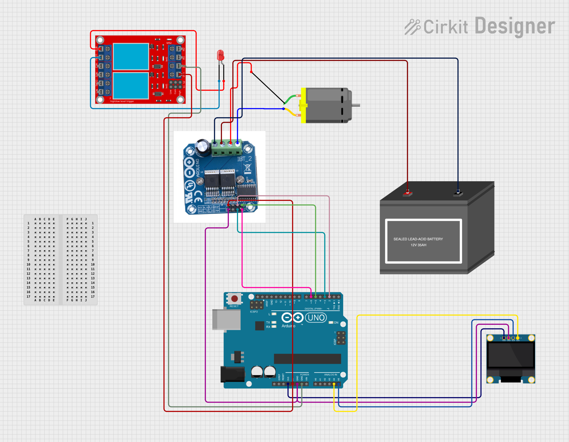
Circuit Documentation
Summary of the Circuit
This circuit is designed to control a DC motor using an Arduino UNO microcontroller and a BTS 7960 motor driver. It also includes an OLED display for user interface, a 2-channel relay module for additional control capabilities, an LED indicator, and a 12V battery as the power source. The Arduino UNO communicates with the OLED display via I2C protocol and controls the motor driver and relay module through its digital I/O pins. The motor driver is connected to the DC motor, allowing for speed and direction control. The relay module is used to switch an external circuit, which is indicated by the LED.
Component List
OLED 128x64 I2C Monochrome Display
- Description: A monochrome OLED display with a resolution of 128x64 pixels, interfaced via I2C.
- Purpose: To provide a user interface for displaying motor and relay status.
Arduino UNO
- Description: A microcontroller board based on the ATmega328P, equipped with digital and analog I/O pins.
- Purpose: To control the motor driver, relay module, and OLED display, as well as to execute the embedded code for the circuit's logic.
DC Motor
- Description: An electric motor that runs on direct current (DC) electricity.
- Purpose: To perform mechanical work as directed by the motor driver.
BTS 7960 Motor Driver
- Description: A high-power motor driver capable of driving large loads with current and speed control.
- Purpose: To control the speed and direction of the DC motor.
2-Channel Relay Module
- Description: A module with two relays that can switch AC or DC loads.
- Purpose: To control external circuits, potentially for power management or other actuation purposes.
LED: Two Pin (red)
- Description: A basic red LED with an anode and cathode.
- Purpose: To serve as an indicator light, showing the status of the relay module.
12V Battery (mini)
- Description: A compact 12V battery.
- Purpose: To provide power to the motor driver and, indirectly, to the DC motor.
Wiring Details
OLED 128x64 I2C Monochrome Display
- VDD: Connected to Arduino UNO's 3.3V.
- GND: Connected to Arduino UNO's GND.
- SCK: Connected to Arduino UNO's A5 (SCL).
- SDA: Connected to Arduino UNO's A4 (SDA).
Arduino UNO
- 3.3V: Provides power to the OLED display.
- 5V: Provides power to the BTS 7960 motor driver and the 2-channel relay module.
- GND: Common ground for the OLED display, BTS 7960 motor driver, and 2-channel relay module.
- A4 (SDA): I2C data line for the OLED display.
- A5 (SCL): I2C clock line for the OLED display.
- D2: Connected to BTS 7960's R_EN.
- D3: Connected to BTS 7960's L_En.
- D5: Connected to BTS 7960's RPWM.
- D6: Connected to BTS 7960's LPMW.
DC Motor
- Pin 1: Connected to BTS 7960's M+.
- Pin 2: Connected to BTS 7960's M-.
BTS 7960 Motor Driver
- VCC: Connected to Arduino UNO's 5V.
- GND: Connected to Arduino UNO's GND.
- R_EN: Connected to Arduino UNO's D2.
- RPWM: Connected to Arduino UNO's D5.
- LPMW: Connected to Arduino UNO's D6.
- L_En: Connected to Arduino UNO's D3.
- M+: Connected to DC Motor's Pin 1.
- M-: Connected to DC Motor's Pin 2.
- B+: Connected to 12V Battery's +.
- B-: Connected to 12V Battery's -.
2-Channel Relay Module
- VCC+: Connected to Arduino UNO's 5V.
- VCC- (GND): Connected to Arduino UNO's GND.
- N.O. 2: Connected to LED's anode.
- COM 2: Connected to LED's cathode.
LED: Two Pin (red)
- Anode: Connected to 2-channel relay module's N.O. 2.
- Cathode: Connected to 2-channel relay module's COM 2.
12V Battery (mini)
- +: Connected to BTS 7960's B+.
- -: Connected to BTS 7960's B-.
Documented Code
#include <U8glib.h>
#include <Wire.h>

// OLED setup
U8GLIB_SH1106_128X64 oled(U8G_I2C_OPT_NONE);

// Pins for the AC relay
const int relayPin = 7;

// Timing intervals for the AC relay (in milliseconds)
const unsigned long relayOnTime = 10000;   // 10 seconds = 10,000 milliseconds
const unsigned long relayOffTime = 10000;  // 10 seconds = 10,000 milliseconds

// Pins for motor control
int r_en = 2;
int l_en = 3;
int r_pwm = 5;
int l_pwm = 6;

// Timing intervals for the motors (in milliseconds)
const unsigned long motorRunTime = 10000; // 10 seconds = 10,000 milliseconds
const unsigned long motorOffTime = 10000; // 10 seconds = 10,000 milliseconds

// Variables to keep track of time
unsigned long relayStartMillis = 0;
unsigned long motorStartMillis = 0;
bool relayState = false;
bool motorState = false;

void setup(void) {
  // Initialize the relay pin as an output
  pinMode(relayPin, OUTPUT);

  // Initialize motor control pins as outputs
  pinMode(r_en, OUTPUT);
  pinMode(l_en, OUTPUT);
  pinMode(r_pwm, OUTPUT);
  pinMode(l_pwm, OUTPUT);

  // Start with relay off and motors off
  digitalWrite(relayPin, LOW);
  digitalWrite(r_en, LOW);
  digitalWrite(l_en, LOW);
  analogWrite(r_pwm, 0);
  analogWrite(l_pwm, 0);

  // Start motor immediately for testing
  motorStartMillis = millis();
  motorState = true;
  digitalWrite(r_en, HIGH);
  digitalWrite(l_en, HIGH);
  analogWrite(r_pwm, 45);  // Example PWM value for RPM calculation
  analogWrite(l_pwm, 0);
}

void loop(void) {
  unsigned long currentMillis = millis();

  // Relay control
  if (relayState && currentMillis - relayStartMillis >= relayOnTime) {
    relayState = false;
    relayStartMillis = currentMillis;
    digitalWrite(relayPin, LOW);
  } else if (!relayState && currentMillis - relayStartMillis >= relayOffTime) {
    relayState = true;
    relayStartMillis = currentMillis;
    digitalWrite(relayPin, HIGH);
  }

  // Motor control
  if (motorState && currentMillis - motorStartMillis >= motorRunTime) {
    motorState = false;
    motorStartMillis = currentMillis;
    analogWrite(r_pwm, 0);
    analogWrite(l_pwm, 0);
    digitalWrite(r_en, LOW);
    digitalWrite(l_en, LOW);
  } else if (!motorState && currentMillis - motorStartMillis >= motorOffTime) {
    motorState = true;
    motorStartMillis = currentMillis;
    digitalWrite(r_en, HIGH);
    digitalWrite(l_en, HIGH);
    analogWrite(r_pwm, 45);  // Example PWM value for RPM calculation
    analogWrite(l_pwm, 0);
  }

  // Display the info on the OLED screen
  oled.firstPage();
  do {
    displayInfo(currentMillis);
  } while (oled.nextPage());

  delay(1000);  // Update the display every second
}

// Function to display RPM and timer info on the OLED screen
void displayInfo(unsigned long currentMillis) {
  // Calculate elapsed times
  unsigned long relayElapsedTime = relayState ? (currentMillis - relayStartMillis) : (relayOffTime - (currentMillis - relayStartMillis));
  unsigned long motorElapsedTime = motorState ? (currentMillis - motorStartMillis) : (motorOffTime - (currentMillis - motorStartMillis));

  // Calculate RPM (example: pwmValue is fixed at 45 for this case)
  int pwmValue = 45;
  int rpm = pwmValue / 8;

  // Page 1: Display RPM
  oled.setFont(u8g_font_profont12);
  oled.setPrintPos(0, 10);
  oled.print("RPM = ");
  oled.print(rpm);

  // Page 2: Display Motor ON/OFF Time
  oled.setPrintPos(0, 25);
  oled.print(motorState ? "Motor ON = " : "Motor OFF = ");
  oled.print(motorElapsedTime / 1000); // Display in seconds