ESP32-Based Security System with RFID, PIR Sensor, and Laser Detection
Circuit Documentation
Summary of the Circuit
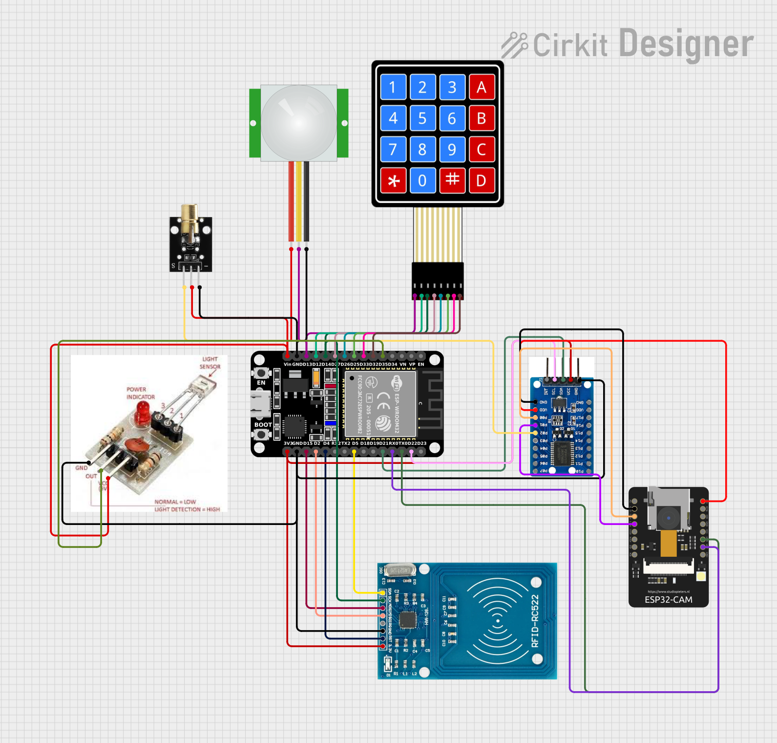
This circuit integrates various components to perform a range of functions. It includes an ESP32 microcontroller as the central processing unit, interfacing with a PIR sensor for motion detection, an RFID-RC522 module for RFID communication, a 4x4 Membrane Matrix Keypad for user input, an ESP32-CAM module for capturing images, a PCF8575 I/O Expander to increase the number of I/O pins, a KY-008 Laser Emitter for emitting laser light, and a Laser Receiver Module to detect the laser light. The circuit is designed to handle input from the keypad, detect motion and RFID tags, manage image capture, and control a laser emitter and receiver.
Component List
ESP32 (30 pin)
- Description: A microcontroller with Wi-Fi and Bluetooth capabilities, featuring a wide range of GPIO pins.
- Pins: EN, VP, VN, D34, D35, D32, D33, D25, D26, D27, D14, D12, D13, GND, Vin, D23, D22, TX0, RX0, D21, D19, D18, D5, TX2, RX2, D4, D2, D15, 3V3
PIR Sensor
- Description: A passive infrared sensor that detects motion by measuring changes in the infrared levels emitted by surrounding objects.
- Pins: VDD, SIG, GND
RFID-RC522
- Description: An RFID reader/writer module for interfacing with RFID tags.
- Pins: VCC (3.3V), RST, GND, IRQ, MISO, MOSI, SCK, SDA
4X4 Membrane Matrix Keypad
- Description: A 16-button keypad that provides a simple user interface for input.
- Pins: R1, R2, R3, R4, C1, C2, C3, C4
ESP32-CAM
- Description: A small-sized ESP32-based camera module that is suitable for smart home devices and IoT applications.
- Pins: 5V, GND, IO12, IO13, IO15, IO14, IO2, IO4, VOT, VOR, VCC, IO0, IO16, 3V3
PCF8575 I/O Expander
- Description: An I2C interface I/O expander that provides additional GPIOs.
- Pins: GND, VDD, P00, P01, P02, P03, P04, P05, P06, P07, P17, P16, P15, P14, P13, P12, P11, P10, INT, SCL, SDA, VCC
KY-008 Laser Emitter
- Description: A module that emits a small and focused beam of laser light.
- Pins: SIG, 5V, GND
Laser Receiver Module
- Description: A module that detects laser light and outputs a signal when the light is detected.
- Pins: VCC, OUTPUT, GROUND
Wiring Details
ESP32 (30 pin)
- D35 connected to Laser Receiver Module OUTPUT
- D32 connected to 4X4 Membrane Matrix Keypad C4
- D33 connected to 4X4 Membrane Matrix Keypad C3
- D25 connected to 4X4 Membrane Matrix Keypad C2
- D26 connected to 4X4 Membrane Matrix Keypad C1
- D27 connected to 4X4 Membrane Matrix Keypad R4
- D14 connected to 4X4 Membrane Matrix Keypad R3 and RFID-RC522 SCK
- D12 connected to 4X4 Membrane Matrix Keypad R2
- D13 connected to 4X4 Membrane Matrix Keypad R1 and PIR Sensor SIG
- GND connected to PIR Sensor GND, KY-008 Laser Emitter GND, PCF8575 IO Expander GND, Laser Receiver Module GROUND, RFID-RC522 GND
- Vin connected to PIR Sensor VDD, Laser Receiver Module VCC, KY-008 Laser Emitter 5V
- D22 connected to PCF8575 IO Expander SCL
- TX0 connected to ESP32-CAM VOR
- RX0 connected to ESP32-CAM VOT
- D21 connected to PCF8575 IO Expander SDA
- D5 connected to RFID-RC522 SDA
- D4 connected to RFID-RC522 RST
- D2 connected to RFID-RC522 MISO
- D15 connected to RFID-RC522 MOSI
- 3V3 connected to PCF8575 IO Expander VCC and RFID-RC522 VCC (3.3V)
PIR Sensor
- VDD connected to ESP32 Vin
- SIG connected to ESP32 D13
- GND connected to ESP32 GND
RFID-RC522
- VCC (3.3V) connected to ESP32 3V3
- RST connected to ESP32 D4
- GND connected to ESP32 GND
- IRQ not connected
- MISO connected to ESP32 D2
- MOSI connected to ESP32 D15
- SCK connected to ESP32 D14
- SDA connected to ESP32 D5
4X4 Membrane Matrix Keypad
- C4 connected to ESP32 D32
- C3 connected to ESP32 D33
- C2 connected to ESP32 D25
- C1 connected to ESP32 D26
- R4 connected to ESP32 D27
- R3 connected to ESP32 D14
- R2 connected to ESP32 D12
- R1 connected to ESP32 D13
ESP32-CAM
- 5V not connected
- GND connected to PCF8575 IO Expander GND
- IO12 connected to PCF8575 IO Expander P00
- IO13 connected to PCF8575 IO Expander P01
- IO15 not connected
- IO14 not connected
- IO2 not connected
- IO4 not connected
- VOT connected to ESP32 RX0
- VOR connected to ESP32 TX0
- VCC not connected
- IO0 not connected
- IO16 not connected
- 3V3 connected to PCF8575 IO Expander VDD
PCF8575 IO Expander
- GND connected to ESP32 GND and Laser Receiver Module GROUND
- VDD connected to ESP32-CAM 3V3
- P00 connected to ESP32-CAM IO12
- P01 connected to ESP32-CAM IO13
- P02 connected to KY-008 Laser Emitter SIG
- P03 to P17 not connected
- INT not connected
- SCL connected to ESP32 D22
- SDA connected to ESP32 D21
- VCC connected to ESP32 3V3
KY-008 Laser Emitter
- SIG connected to PCF8575 IO Expander P02
- 5V connected to ESP32 Vin
- GND connected to ESP32 GND
Laser Receiver Module
- VCC connected to ESP32 Vin
- OUTPUT connected to ESP32 D35
- GROUND connected to ESP32 GND
Documented Code
No code has been provided for the microcontrollers in the circuit. If code is available, it should be documented here with explanations for each function and how it interacts with the connected hardware components.