
Arduino UNO Controlled 775 Motor with Rotary Encoder and 7-Segment Display Timer
View and Edit Project In Cirkit Designer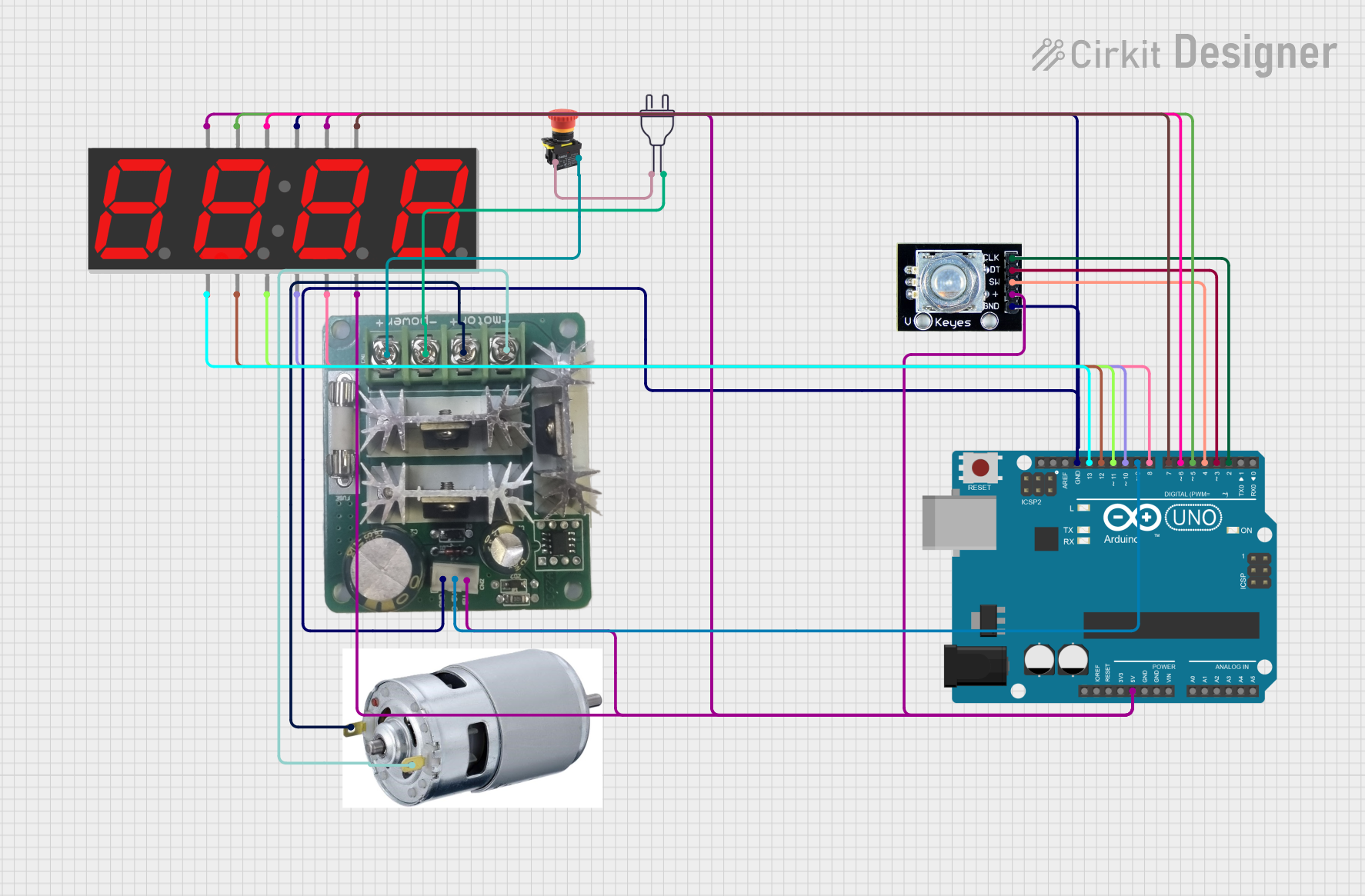
Circuit Documentation
Summary
This circuit is designed to control a 775 motor using a PWM DC motor controller. The motor operation is controlled by a rotary encoder, which sets the runtime for the motor. The runtime is displayed on a 4-digit 7-segment display. The motor starts when the rotary encoder's knob is pushed in and runs for the user-defined runtime. The motor will not start again until the knob is pushed in again after the timer is up. The timer is set to a default of 10 minutes when the Arduino receives power.
Component List
Arduino UNO
- Description: Microcontroller board based on the ATmega328P.
- Pins: UNUSED, IOREF, Reset, 3.3V, 5V, GND, Vin, A0, A1, A2, A3, A4, A5, SCL, SDA, AREF, D13, D12, D11, D10, D9, D8, D7, D6, D5, D4, D3, D2, D1, D0
Rotary Encoder
- Description: Device used to set the runtime for the motor.
- Pins: clk, dt, sw, gnd, +
775 Motor
- Description: High-torque DC motor.
- Pins: positive, negative
BDC PWM DC Motor Controller 10A 6-90V
- Description: Motor controller used to control the speed of the 775 motor.
- Pins: + power, - power, + motor, - motor, GND, 0-5V, 5V
Power 220V
- Description: Power supply for the circuit.
- Pins: hot wire, neutral wire
Emergency STOP
- Description: Safety switch to cut off power in case of an emergency.
- Pins: NC
7 Segment Display (4 Digit)
- Description: Display used to show the countdown timer.
- Pins: 1, A, F, 2, 3, B, G, 4, C, DP, D, E
Wiring Details
Arduino UNO
5V connected to:
- 7 Segment Display (4 Digit) pin 1
- 7 Segment Display (4 Digit) pin 3
- 7 Segment Display (4 Digit) pin 4
- BDC PWM DC Motor Controller 10A 6-90V pin 5V
- Rotary Encoder pin +
GND connected to:
- 7 Segment Display (4 Digit) pin 2
- BDC PWM DC Motor Controller 10A 6-90V pin GND
- Rotary Encoder pin gnd
D13 connected to 7 Segment Display (4 Digit) pin E
D12 connected to 7 Segment Display (4 Digit) pin D
D11 connected to 7 Segment Display (4 Digit) pin DP
D10 connected to 7 Segment Display (4 Digit) pin C
D9 connected to BDC PWM DC Motor Controller 10A 6-90V pin 0-5V
D8 connected to 7 Segment Display (4 Digit) pin G
D7 connected to 7 Segment Display (4 Digit) pin B
D6 connected to 7 Segment Display (4 Digit) pin F
D5 connected to 7 Segment Display (4 Digit) pin A
D4 connected to Rotary Encoder pin sw
D3 connected to Rotary Encoder pin dt
D2 connected to Rotary Encoder pin clk
Rotary Encoder
clk connected to Arduino UNO pin D2
dt connected to Arduino UNO pin D3
sw connected to Arduino UNO pin D4
gnd connected to Arduino UNO pin GND
+ connected to Arduino UNO pin 5V
775 Motor
positive connected to BDC PWM DC Motor Controller 10A 6-90V pin + motor
negative connected to BDC PWM DC Motor Controller 10A 6-90V pin - motor
BDC PWM DC Motor Controller 10A 6-90V
+ power connected to Emergency STOP pin NC
- power connected to Power 220V pin neutral wire
+ motor connected to 775 Motor pin positive
- motor connected to 775 Motor pin negative
GND connected to Arduino UNO pin GND
0-5V connected to Arduino UNO pin D9
5V connected to Arduino UNO pin 5V
Power 220V
hot wire connected to Emergency STOP pin NC
neutral wire connected to BDC PWM DC Motor Controller 10A 6-90V pin - power
Emergency STOP
- NC connected to:
- Power 220V pin hot wire
- BDC PWM DC Motor Controller 10A 6-90V pin + power
7 Segment Display (4 Digit)
1 connected to Arduino UNO pin 5V
A connected to Arduino UNO pin D5
F connected to Arduino UNO pin D6
2 connected to Arduino UNO pin GND
3 connected to Arduino UNO pin 5V
B connected to Arduino UNO pin D7
G connected to Arduino UNO pin D8
4 connected to Arduino UNO pin 5V
C connected to Arduino UNO pin D10
DP connected to Arduino UNO pin D11
D connected to Arduino UNO pin D12
E connected to Arduino UNO pin D13
Documented Code
/*
 * This Arduino sketch controls a 775 motor using a PWM DC motor controller.
 * The motor starts when the rotary encoder's knob is pushed in and runs for
 * a user-defined runtime set by the rotary encoder. The motor will not start
 * again until the knob is pushed in again after the timer is up. The countdown
 * timer is displayed on a 4-digit 7-segment display. The timer is set to a
 * default of 10 minutes when the Arduino receives power.
 */

#define ENCODER_CLK 2
#define ENCODER_DT 3
#define ENCODER_SW 4
#define MOTOR_PWM 9

#define SEG_A 5
#define SEG_F 6
#define SEG_B 7
#define SEG_G 8
#define SEG_C 10
#define SEG_DP 11
#define SEG_D 12
#define SEG_E 13

volatile int encoderPos = 0;
volatile int lastEncoded = 0;
int runtimeMinutes = 10; // Default runtime in minutes
bool motorRunning = false;
bool buttonPressed = false;

void setup() {
  pinMode(ENCODER_CLK, INPUT);
  pinMode(ENCODER_DT, INPUT);
  pinMode(ENCODER_SW, INPUT);
  pinMode(MOTOR_PWM, OUTPUT);

  pinMode(SEG_A, OUTPUT);
  pinMode(SEG_F, OUTPUT);
  pinMode(SEG_B, OUTPUT);
  pinMode(SEG_G, OUTPUT);
  pinMode(SEG_C, OUTPUT);
  pinMode(SEG_DP, OUTPUT);
  pinMode(SEG_D, OUTPUT);
  pinMode(SEG_E, OUTPUT);

  attachInterrupt(digitalPinToInterrupt(ENCODER_CLK), updateEncoder, CHANGE);
  attachInterrupt(digitalPinToInterrupt(ENCODER_DT), updateEncoder, CHANGE);
}

void loop() {
  if (digitalRead(ENCODER_SW) == LOW && !buttonPressed) {
    buttonPressed = true;
    if (!motorRunning) {
      motorRunning = true;
      runtimeMinutes = encoderPos; // Set runtime based on encoder position
      for (int speed = 0; speed <= 255; speed++) {
        analogWrite(MOTOR_PWM, speed);
        int delayTime = (runtimeMinutes * 60000) / 255; // Runtime in ms / 255 steps
        for (int i = delayTime; i > 0; i -= 1000) {
          displayCountdown(i / 1000);
          delay(1000);
        }
      }
      analogWrite(MOTOR_PWM, 0); // Turn off motor
      motorRunning = false;
    }
  }
  if (digitalRead(ENCODER_SW) == HIGH) {
    buttonPressed = false;
  }
}

void updateEncoder() {
  int MSB = digitalRead(ENCODER_CLK); // MSB = most significant bit
  int LSB = digitalRead(ENCODER_DT);  // LSB = least significant bit

  int encoded = (MSB << 1