Arduino UNO Based GSM-Controlled Dual RGB Color Sensor System
Circuit Documentation
Summary of the Circuit
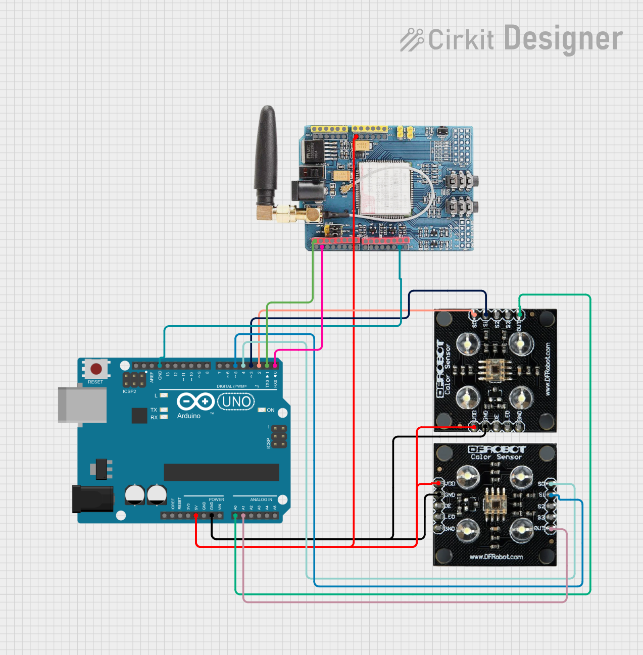
This circuit integrates an Arduino UNO microcontroller with two RGB Colour Sensors and a GSM SIM900 module. The purpose of the circuit is to detect colors using the RGB sensors and communicate this information via SMS using the GSM module. The Arduino UNO is programmed to read color values from the sensors and send updates to a predefined phone number. Additionally, the GSM module can receive text messages, and if the message contains the word 'STATE', it will reply with the last recorded color values from both sensors.
Component List
Arduino UNO
- Description: A microcontroller board based on the ATmega328P.
- Purpose: Acts as the central processing unit for the circuit, interfacing with the RGB sensors and GSM module, and running the embedded code to perform color detection and communication.
GSM SIM900
- Description: A GSM/GPRS module that allows for cellular communication.
- Purpose: Used to send SMS messages with color detection results and receive SMS commands to report the sensor state.
RGB Colour Sensor (x2)
- Description: A sensor that detects the color of objects.
- Purpose: To detect the color of objects and provide this information to the Arduino UNO for processing and subsequent communication via the GSM module.
Wiring Details
Arduino UNO
- 5V: Connected to the Vcc of both RGB Colour Sensors and the 5V of the GSM SIM900 module.
- GND: Common ground shared with both RGB Colour Sensors and the GSM SIM900 module.
- A0: Receives the color output from the first RGB Colour Sensor.
- A1: Receives the color output from the second RGB Colour Sensor.
- D0: Connected to the D1 pin of the GSM SIM900 module (TX).
- D1: Connected to the D0 pin of the GSM SIM900 module (RX).
- D2: Connected to the S0 pin of the first RGB Colour Sensor.
- D3: Connected to the S1 pin of the first RGB Colour Sensor.
- D4: Connected to the S0 pin of the second RGB Colour Sensor.
- D5: Connected to the S1 pin of the second RGB Colour Sensor.
GSM SIM900
- 5V: Receives power from the 5V output of the Arduino UNO.
- GND: Connected to the common ground on the Arduino UNO.
- D0: Connected to the D1 pin (RX) of the Arduino UNO.
- D1: Connected to the D0 pin (TX) of the Arduino UNO.
RGB Colour Sensor 1
- Vcc: Powered by the 5V output from the Arduino UNO.
- GND: Connected to the common ground on the Arduino UNO.
- OUT: Sends the color detection output to the A0 pin on the Arduino UNO.
- S0: Controlled by the D2 pin on the Arduino UNO.
- S1: Controlled by the D3 pin on the Arduino UNO.
RGB Colour Sensor 2
- Vcc: Powered by the 5V output from the Arduino UNO.
- GND: Connected to the common ground on the Arduino UNO.
- OUT: Sends the color detection output to the A1 pin on the Arduino UNO.
- S0: Controlled by the D4 pin on the Arduino UNO.
- S1: Controlled by the D5 pin on the Arduino UNO.
Documented Code
/*
 * This Arduino sketch interfaces with two RGB color sensors and a GSM SIM900 module.
 * The first RGB sensor has S0 and S1 connected to D2 and D3, and output to A0.
 * The second RGB sensor has S0 and S1 connected to D4 and D5, and output to A1.
 * Detected colors are sent via GSM to the number +237671693917.
 * If the GSM module receives a text with the word 'STATE', it replies with the
 * last recorded color from both sensors.
 */

#include <SoftwareSerial.h>

// Pin definitions
const int S0_1 = 2;
const int S1_1 = 3;
const int OUT_1 = A0;
const int S0_2 = 4;
const int S1_2 = 5;
const int OUT_2 = A1;
const char phoneNumber[] = "+237671693917";

SoftwareSerial gsm(0, 1); // RX, TX
String lastColor1 = "";
String lastColor2 = "";

void setup() {
  pinMode(S0_1, OUTPUT);
  pinMode(S1_1, OUTPUT);
  pinMode(S0_2, OUTPUT);
  pinMode(S1_2, OUTPUT);
  Serial.begin(9600);
  gsm.begin(9600);
  delay(1000);
  sendSMS(phoneNumber, "System Initialized");
}

void loop() {
  lastColor1 = readColor(S0_1, S1_1, OUT_1);
  lastColor2 = readColor(S0_2, S1_2, OUT_2);
  sendSMS(phoneNumber, "Color1: " + lastColor1 + ", Color2: " + lastColor2);
  delay(5000);
  if (gsm.available()) {
    String msg = gsm.readString();
    if (msg.indexOf("STATE") >= 0) {
      sendSMS(phoneNumber, "Last Color1: " + lastColor1 + ", Last Color2: " + lastColor2);
    }
  }
}

String readColor(int S0, int S1, int OUT) {
  digitalWrite(S0, HIGH);
  digitalWrite(S1, LOW);
  int red = pulseIn(OUT, LOW);
  digitalWrite(S1, HIGH);
  int green = pulseIn(OUT, LOW);
  digitalWrite(S0, LOW);
  int blue = pulseIn(OUT, LOW);
  return "R:" + String(red) + " G:" + String(green) + " B:" + String(blue);
}

void sendSMS(const char* number, String text) {
  gsm.print("AT+CMGF=1\r");
  delay(100);
  gsm.print("AT+CMGS=\"");
  gsm.print(number);
  gsm.print("\"\r");
  delay(100);
  gsm.print(text);
  delay(100);
  gsm.write(26);
  delay(1000);
}
This code is responsible for initializing the sensors and GSM module, reading color data from the sensors, and sending this data via SMS. It also listens for incoming SMS messages and responds with the last known color states when prompted.