Arduino Nano-Based Line Following Robot with Dual DC Motors and IR Sensor Array
Circuit Documentation
Summary
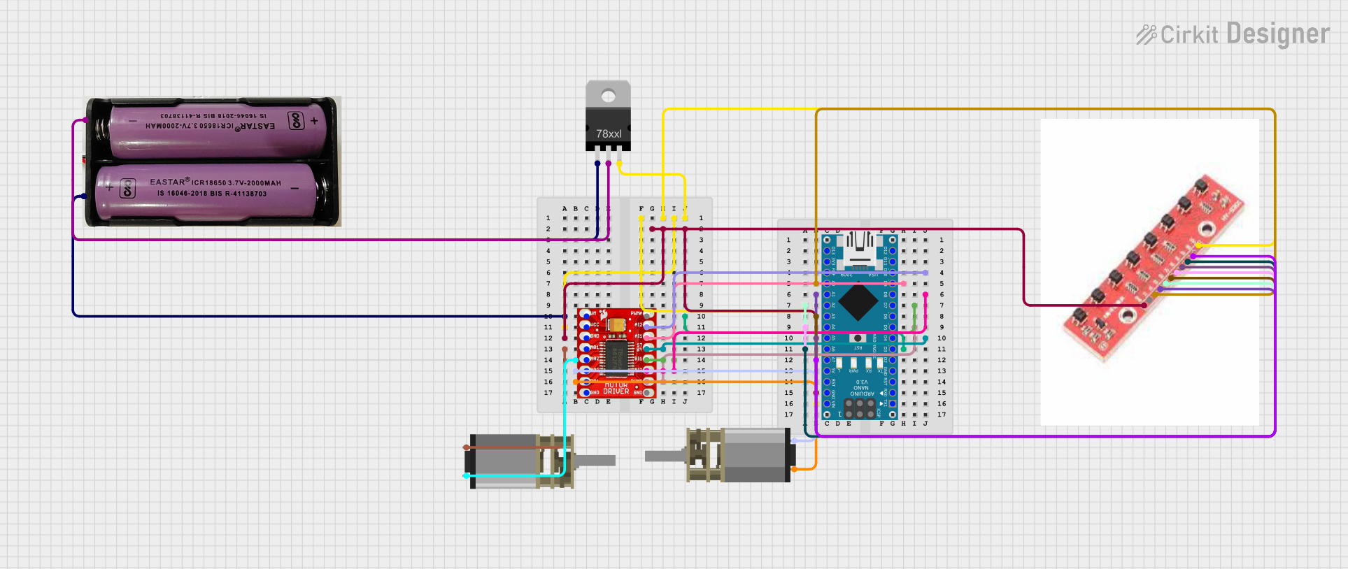
This document provides a detailed overview of a circuit that includes an Arduino Nano, a TB6612FNG Motor Driver, two DC Mini Metal Gear Motors, a Voltage Regulator, a 7.4V battery, and an 8-array IR sensor. The circuit is designed to control the motors using the motor driver, with the Arduino Nano serving as the main controller. The IR sensor is used for detecting obstacles or line following, and the voltage regulator ensures the correct voltage levels for the components.
Component List
DC Mini Metal Gear Motor
- Description: A small, high-torque motor used for driving mechanical components.
- Pins: IN1, IN2
TB6612FNG Motor Driver
- Description: A dual motor driver capable of driving two DC motors with forward and reverse control.
- Pins: GND, B01, B02, A02, A01, VCC, VM, PWMB, BI2, BI1, STBY, AI1, AI2, PWMA
7.4V Battery
- Description: A power source for the circuit.
- Pins: +, -
Arduino Nano
- Description: A small, complete, and breadboard-friendly microcontroller board based on the ATmega328P.
- Pins: D1/TX, D0/RX, RESET, GND, D2, D3, D4, D5, D6, D7, D8, D9, D10, D11/MOSI, D12/MISO, VIN, 5V, A7, A6, A5, A4, A3, A2, A1, A0, AREF, 3V3, D13/SCK
Voltage Regulator
- Description: A component that regulates the voltage to a desired level.
- Pins: IN, GND, OUT
8-array IR Sensor
- Description: An array of infrared sensors used for detecting obstacles or line following.
- Pins: (No specific pin labels provided)
Wiring Details
DC Mini Metal Gear Motor 1
- IN1 connected to B01 of TB6612FNG Motor Driver
- IN2 connected to B02 of TB6612FNG Motor Driver
DC Mini Metal Gear Motor 2
- IN1 connected to A01 of TB6612FNG Motor Driver
- IN2 connected to A02 of TB6612FNG Motor Driver
TB6612FNG Motor Driver
- GND connected to GND of Arduino Nano and 8-array IR Sensor
- VCC connected to VIN of Arduino Nano, OUT of Voltage Regulator, and 8-array IR Sensor
- VM connected to IN of Voltage Regulator and + of 7.4V Battery
- PWMB connected to D5 of Arduino Nano
- BI2 connected to D8 of Arduino Nano
- BI1 connected to D7 of Arduino Nano
- STBY connected to D4 of Arduino Nano
- AI1 connected to D9 of Arduino Nano
- AI2 connected to D10 of Arduino Nano
7.4V Battery
- + connected to IN of Voltage Regulator
- - connected to GND of Voltage Regulator
Arduino Nano
- D10 connected to AI2 of TB6612FNG Motor Driver
- A0 connected to 8-array IR Sensor
- D9 connected to AI1 of TB6612FNG Motor Driver
- A1 connected to 8-array IR Sensor
- D8 connected to BI2 of TB6612FNG Motor Driver
- A2 connected to 8-array IR Sensor
- D7 connected to BI1 of TB6612FNG Motor Driver
- A3 connected to 8-array IR Sensor
- A4 connected to 8-array IR Sensor
- D5 connected to PWMB of TB6612FNG Motor Driver
- A5 connected to 8-array IR Sensor
- D4 connected to STBY of TB6612FNG Motor Driver
- A6 connected to 8-array IR Sensor
- A7 connected to 8-array IR Sensor
- GND connected to GND of TB6612FNG Motor Driver and 8-array IR Sensor
- VIN connected to VCC of TB6612FNG Motor Driver, OUT of Voltage Regulator, and 8-array IR Sensor
Voltage Regulator
- IN connected to + of 7.4V Battery and VM of TB6612FNG Motor Driver
- GND connected to - of 7.4V Battery
- OUT connected to VCC of TB6612FNG Motor Driver, VIN of Arduino Nano, and 8-array IR Sensor
8-array IR Sensor
- Connected to: A0, A1, A2, A3, A4, A5, A6, A7, GND, and VCC of Arduino Nano
Documented Code
Arduino Nano Code (sketch.ino)
void setup() {
  // put your setup code here, to run once:

}

void loop() {
  // put your main code here, to run repeatedly:

}
This code is a basic template for the Arduino Nano. The setup() function is where you initialize your components and settings, and the loop() function is where the main logic of your program runs repeatedly. You can add your motor control and sensor reading logic in these functions.
This document provides a comprehensive overview of the circuit, including the components used, their connections, and the initial code for the Arduino Nano. This should serve as a solid foundation for further development and testing of the circuit.