
Circuit Documentation
Summary
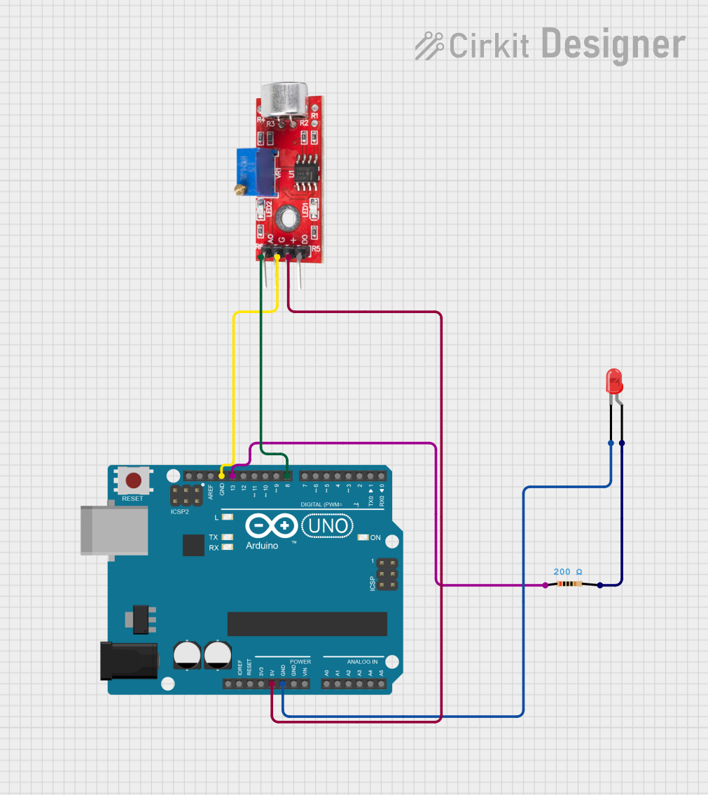
This circuit consists of an Arduino UNO microcontroller, a sound sensor, a red LED, and a resistor. The sound sensor detects sound levels and sends an analog signal to the Arduino. The Arduino processes this signal and controls the LED, turning it on or off based on the sound level.
Component List
Sound Sensor
- Description: A sensor that detects sound levels and outputs an analog signal.
- Pins: Analog, GND, VCC, Digital
Arduino UNO
- Description: A microcontroller board based on the ATmega328P.
- Pins: UNUSED, IOREF, Reset, 3.3V, 5V, GND, Vin, A0, A1, A2, A3, A4, A5, SCL, SDA, AREF, D13, D12, D11, D10, D9, D8, D7, D6, D5, D4, D3, D2, D1, D0
LED: Two Pin (red)
- Description: A red light-emitting diode.
- Pins: Cathode, Anode
Resistor
- Description: A resistor with a resistance of 200 Ohms.
- Pins: Pin1, Pin2
- Properties:
- Resistance: 200 Ohms
Wiring Details
Sound Sensor
- Analog pin connected to D8 pin of Arduino UNO
- GND pin connected to GND pin of Arduino UNO
- VCC pin connected to 5V pin of Arduino UNO
Arduino UNO
- D8 pin connected to Analog pin of Sound Sensor
- GND pin connected to GND pin of Sound Sensor
- 5V pin connected to VCC pin of Sound Sensor
- GND pin connected to Cathode pin of LED: Two Pin (red)
- D13 pin connected to Pin1 pin of Resistor
LED: Two Pin (red)
- Cathode pin connected to GND pin of Arduino UNO
- Anode pin connected to Pin2 pin of Resistor
Resistor
- Pin1 pin connected to D13 pin of Arduino UNO
- Pin2 pin connected to Anode pin of LED: Two Pin (red)
Documented Code
Arduino UNO Code (sketch.ino)
void setup() {
  // put your setup code here, to run once:

}

void loop() {
  // put your main code here, to run repeatedly:

}
Documentation (documentation.txt)
This documentation provides a comprehensive overview of the circuit, including a summary, detailed component descriptions, wiring details, and the code used in the microcontroller.