
Raspberry Pi 4B-Based IR Sensor and Servomotor Control System with Indicator LEDs
View and Edit Project In Cirkit Designer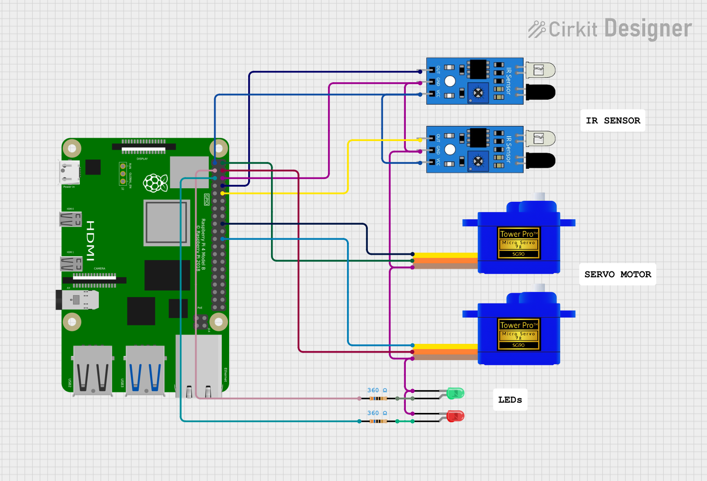
Circuit Documentation
Summary
The circuit in question is designed to interface a Raspberry Pi 4B with multiple peripheral devices, including two IR sensors, two servomotors, and two LEDs (one green and one red). The Raspberry Pi 4B serves as the central processing unit, controlling the servomotors based on inputs from the IR sensors and indicating status through the LEDs. The servomotors are powered by the 5V supply from the Raspberry Pi, while the IR sensors are powered by the 3.3V supply. The LEDs are connected to GPIO pins through resistors to limit the current. Ground connections are shared among all components.
Component List
Raspberry Pi 4B
- Microcontroller with multiple GPIO pins, providing 3.3V and 5V power outputs.
- Used as the main controller for interfacing with sensors, driving servomotors, and controlling LEDs.
IR Sensor (x2)
- Sensor with digital output to detect the presence of objects.
- Connected to the Raspberry Pi for object detection.
Servomotor SG90 (x2)
- Small and lightweight servomotor for precise angular movement.
- Controlled by the Raspberry Pi to perform actions based on sensor inputs.
LED: Two Pin (Green)
- A green LED used to indicate a specific status or condition.
- Driven by a GPIO pin on the Raspberry Pi through a current-limiting resistor.
LED: Two Pin (Red)
- A red LED used to indicate a different status or condition than the green LED.
- Also driven by a GPIO pin on the Raspberry Pi through a current-limiting resistor.
Resistor (x2)
- 360 Ohm resistors used to limit the current through the LEDs.
- Ensures that the LEDs are not subjected to excessive current which could damage them.
Wiring Details
Raspberry Pi 4B
3V3connected to both IR sensor VCC pins.5Vconnected to both Servomotor SG90 VCC pins.GPIO2connected to one side of a 360 Ohm resistor.GPIO3connected to one side of another 360 Ohm resistor.GNDconnected to the ground pins of all other components.GPIO14connected to the output of one IR sensor.GPIO15connected to the output of the other IR sensor.GPIO24connected to the signal pin of one Servomotor SG90.GPIO25connected to the signal pin of the other Servomotor SG90.
IR Sensor
VCCconnected to Raspberry Pi3V3.GNDconnected to Raspberry PiGND.outconnected to Raspberry PiGPIO14orGPIO15.
Servomotor SG90
VCCconnected to Raspberry Pi5V.GNDconnected to Raspberry PiGND.SIGconnected to Raspberry PiGPIO24orGPIO25.
LED: Two Pin (Green)
cathodeconnected to Raspberry PiGND.anodeconnected to one side of a 360 Ohm resistor, the other side connected to Raspberry PiGPIO2.
LED: Two Pin (Red)
cathodeconnected to Raspberry PiGND.anodeconnected to one side of a 360 Ohm resistor, the other side connected to Raspberry PiGPIO3.
Resistor
- One side connected to Raspberry Pi
GPIO2orGPIO3. - The other side connected to the anode of the green or red LED, respectively.
Documented Code
No code was provided for the microcontrollers in the circuit. The expected code would typically initialize the GPIO pins, set up the IR sensors for input, configure the servomotors for output, and control the LEDs based on the logic defined for the circuit's operation.