
Arduino Mega 2560-Based Battery-Powered Robotic Vehicle with OLED Display and Sensors
View and Edit Project In Cirkit Designer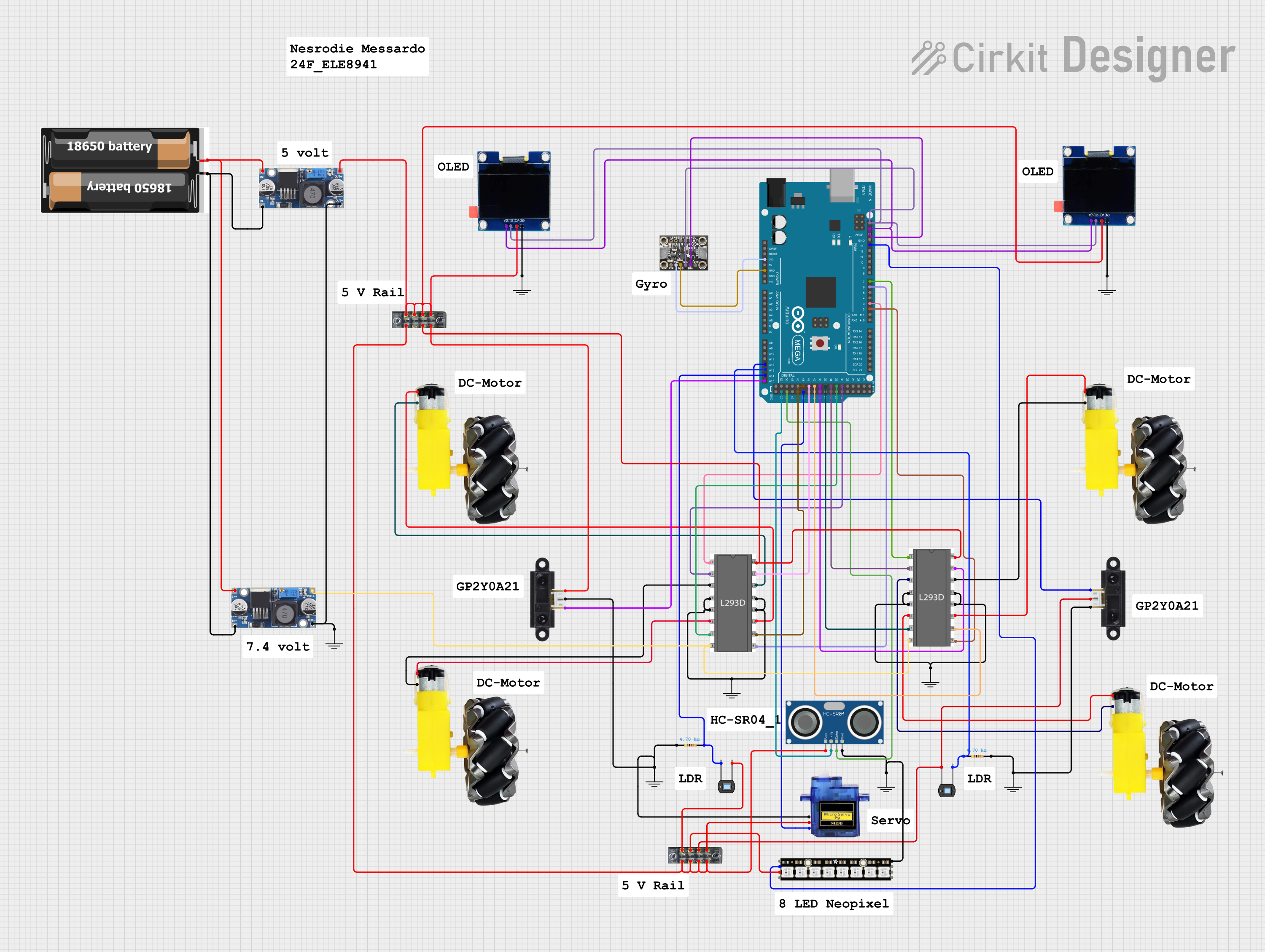
Circuit Documentation
Summary
This document provides a detailed overview of a circuit that includes various sensors, displays, motors, and a microcontroller. The circuit is designed to interface with an Arduino Mega 2560, which controls the components and processes the data from the sensors. The components include OLED displays, ultrasonic sensors, photodiodes, IR sensors, a servo motor, a motor driver, and a NeoPixel stick. The circuit is powered by a 48V to 5V converter and a 2x 18650 battery pack.
Component List
OLED 1.3" Display
- Pins: GND, VCC, SCL, SDA
- Description: A 1.3-inch OLED display used for visual output.
HC-SR04 Ultrasonic Sensor
- Pins: VCC, TRIG, ECHO, GND
- Description: An ultrasonic sensor used for distance measurement.
Photodiode
- Pins: Cathode, Anode
- Description: A photodiode used for light detection.
Micro Servo 9G
- Pins: GND, +5V, PWM
- Description: A small servo motor used for precise control of angular position.
Arduino Mega 2560
- Pins: Multiple I/O pins
- Description: A microcontroller board based on the ATmega2560.
Motor and Wheels
- Pins: VCC, GND
- Description: A motor and wheel assembly for movement.
2x 18650 Battery Pack
- Pins: VCC, GND
- Description: A battery pack providing power to the circuit.
LSM6DS3+LIS3MDL
- Pins: Vin, 3Vo, GND, SCL, SDA, INT2, INT1, INIM, DRDy
- Description: A combined accelerometer and magnetometer sensor.
Sharp IR Sensor
- Pins: VCC, GND, Pin
- Description: An infrared sensor used for distance measurement.
Adafruit NeoPixel Stick
- Pins: GND, DATAOUT, +5V, DATAIN
- Description: An LED stick with individually addressable RGB LEDs.
L293D Motor Driver
- Pins: Enable 1, Input 1, Output 1, GND, Output 2, Input 2, VS, VSS, Input 4, Output 4, Output 3, Input 3, Enable 2
- Description: A motor driver used to control the motors.
Resistor
- Pins: Pin1, Pin2
- Description: A resistor with a resistance of 4700 Ohms.
48V to 5V Converter
- Pins: Out+, Out--, In+, In--
- Description: A voltage converter that steps down 48V to 5V.
Terminal Block
- Pins: 1, 2, 3, 4, 5, 6, 7, 8
- Description: A terminal block for connecting multiple wires.
GND
- Pins: GND
- Description: Ground connection.
Wiring Details
OLED 1.3" Display
- GND connected to GND
- VCC connected to Terminal Block (Pins 1, 3, 5, 7) and 48V to 5V Converter (Out+)
- SCL connected to LSM6DS3+LIS3MDL (SCL), Arduino Mega 2560 (SCL)
- SDA connected to LSM6DS3+LIS3MDL (SDA), Arduino Mega 2560 (SDA)
HC-SR04 Ultrasonic Sensor
- VCC connected to Terminal Block (Pins 2, 4, 6, 8)
- TRIG connected to Arduino Mega 2560 (D53)
- ECHO connected to Arduino Mega 2560 (D51)
- GND connected to GND and Adafruit NeoPixel Stick (GND)
Photodiode
- Cathode connected to Terminal Block (Pin 1)
- Anode connected to Arduino Mega 2560 (A14) and Resistor (Pin2)
Micro Servo 9G
- GND connected to GND
- +5V connected to Terminal Block (Pin 7)
- PWM connected to Arduino Mega 2560 (D45)
Arduino Mega 2560
- 3V3 connected to LSM6DS3+LIS3MDL (3Vo)
- GND connected to LSM6DS3+LIS3MDL (GND)
- A14 connected to Photodiode (Anode)
- A13 connected to Photodiode (Cathode) and Resistor (Pin1)
- A12 connected to Sharp IR Sensor (Pin)
- A15 connected to Sharp IR Sensor (Pin)
- D2 PWM connected to L293D Motor Driver (Enable 2)
- D3 PWM connected to L293D Motor Driver (Enable 1)
- D6 PWM connected to L293D Motor Driver (Enable 2)
- D7 PWM connected to L293D Motor Driver (Enable 1)
- D13 PWM connected to Adafruit NeoPixel Stick (DATAIN)
- D44 connected to L293D Motor Driver (Input 3)
- D42 connected to L293D Motor Driver (Input 4)
- D40 connected to L293D Motor Driver (Input 3)
- D38 connected to L293D Motor Driver (Input 4)
- D36 connected to L293D Motor Driver (Input 2)
- D34 connected to L293D Motor Driver (Input 1)
- D32 connected to L293D Motor Driver (Input 2)
- D30 connected to L293D Motor Driver (Input 1)
Motor and Wheels
- VCC connected to L293D Motor Driver (Output 3, Output 2)
- GND connected to L293D Motor Driver (Output 4, Output 1)
2x 18650 Battery Pack
- VCC connected to 48V to 5V Converter (In+)
- GND connected to 48V to 5V Converter (In--)
LSM6DS3+LIS3MDL
- SCL connected to OLED 1.3" Display (SCL), Arduino Mega 2560 (SCL)
- SDA connected to OLED 1.3" Display (SDA), Arduino Mega 2560 (SDA)
- 3Vo connected to Arduino Mega 2560 (3V3)
- GND connected to Arduino Mega 2560 (GND)
Sharp IR Sensor
- GND connected to Photodiode (Anode), Terminal Block (Pin 5)
- VCC connected to Terminal Block (Pin 8)
- Pin connected to Arduino Mega 2560 (A12, A15)
Adafruit NeoPixel Stick
- GND connected to GND
- DATAIN connected to Arduino Mega 2560 (D13 PWM)
- +5V connected to Terminal Block (Pin 3)
L293D Motor Driver
- Enable 1 connected to Arduino Mega 2560 (D3 PWM, D7 PWM)
- Enable 2 connected to Arduino Mega 2560 (D2 PWM, D6 PWM)
- Input 1 connected to Arduino Mega 2560 (D34, D30)
- Input 2 connected to Arduino Mega 2560 (D36, D32)
- Input 3 connected to Arduino Mega 2560 (D44, D40)
- Input 4 connected to Arduino Mega 2560 (D42, D38)
- Output 1 connected to Motor and Wheels (GND)
- Output 2 connected to Motor and Wheels (VCC)
- Output 3 connected to Motor and Wheels (VCC)
- Output 4 connected to Motor and Wheels (GND)
- VS connected to 48V to 5V Converter (Out+)
- VSS connected to Terminal Block (Pin 6)
- GND connected to GND
Resistor
- Pin1 connected to Photodiode (Cathode), Arduino Mega 2560 (A13)
- Pin2 connected to Photodiode (Anode), Arduino Mega 2560 (A14)
48V to 5V Converter
- Out+ connected to Terminal Block (Pins 1, 3, 5, 7), OLED 1.3" Display (VCC), L293D Motor Driver (VS)
- Out-- connected to GND
- In+ connected to 2x 18650 Battery Pack (V