Cirkit Designer
Your all-in-one circuit design IDE
Home /
Project Documentation
ESP32-Based Ultrasonic Distance Measurement with Buzzer Alert

Circuit Documentation
Summary of the Circuit
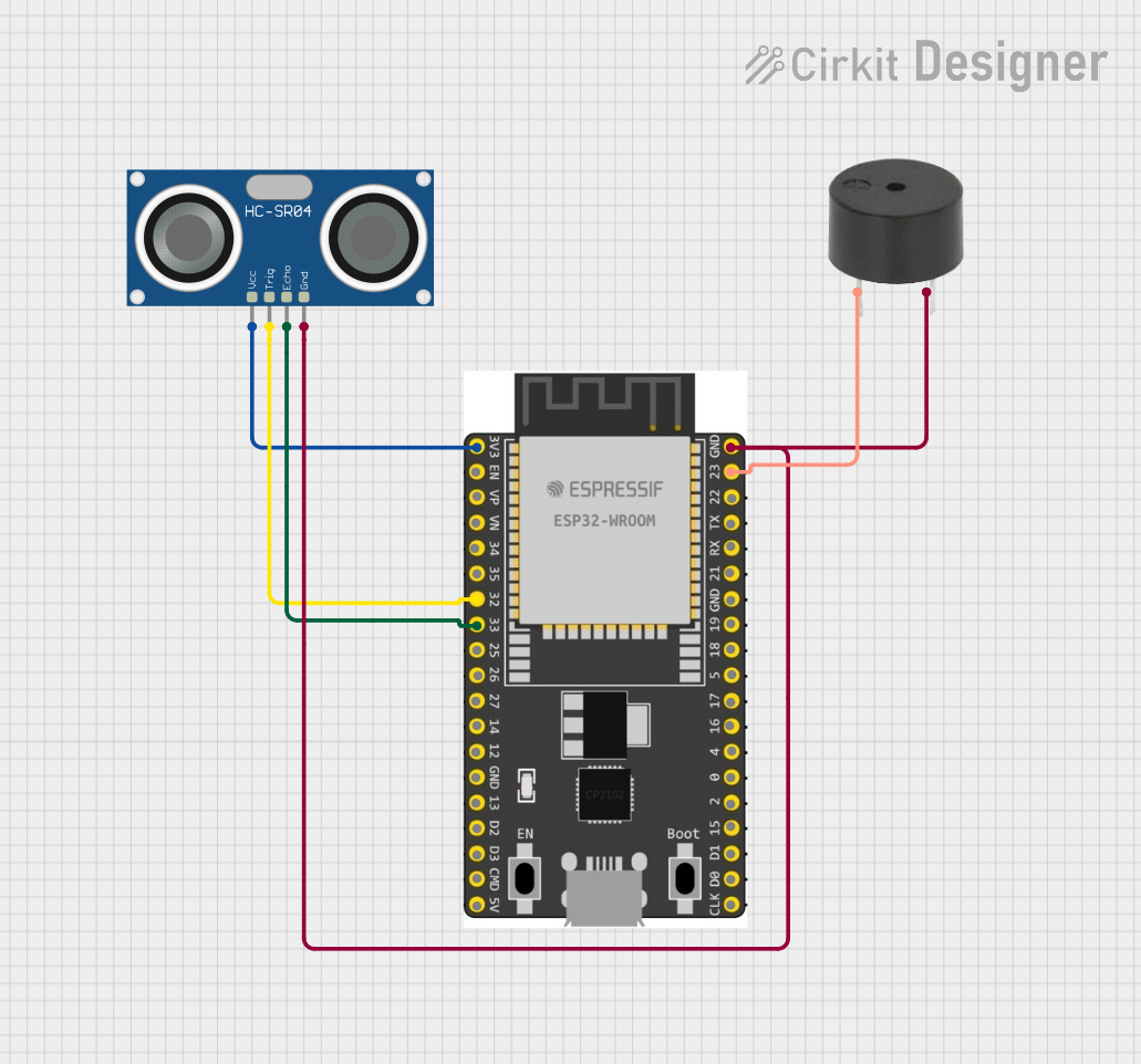
This circuit is designed to interface an HC-SR04 Ultrasonic Sensor with an ESP32 Wroom Dev Kit microcontroller for distance measurement applications. The ESP32 is also connected to a buzzer, which can be used to provide audible feedback based on the distance measurements from the ultrasonic sensor.
Component List
HC-SR04 Ultrasonic Sensor
- Pins: VCC, TRIG, ECHO, GND
- Description: This sensor is used for measuring distances by emitting an ultrasonic wave and measuring the time taken for the echo to return.
- Purpose: To provide distance measurements to the ESP32 microcontroller.
Buzzer
- Pins: PIN, GND
- Description: An electromechanical component that produces sound when an electrical signal is applied.
- Purpose: To generate an audible alert based on the distance measured by the HC-SR04 sensor.
ESP 32 Wroom Dev Kit
- Pins: 3V3, EN, VP, VN, GPIO 34, GPIO 35, GPIO 32, GPIO 33, GPIO 25, GPIO 26, GPIO 27, GPIO 14, GND, GPIO 13, SD2, SD3, CMD, V5, GPIO 23, GPIO 22, TXD, RXD, GPIO 21, GPIO 19, GPIO 18, GPIO 5, GPIO 17, GPIO 16, GPIO 4, GPIO 0, GPIO 2, GPIO 15, SD1, SD0, CLK
- Description: A powerful microcontroller with Wi-Fi and Bluetooth capabilities, suitable for a wide range of IoT applications.
- Purpose: To control the HC-SR04 sensor and the buzzer, and to process the distance measurements.
Wiring Details
HC-SR04 Ultrasonic Sensor
- VCC: Connected to the 3V3 pin of the ESP32 Wroom Dev Kit.
- TRIG: Connected to the GPIO 32 pin of the ESP32 Wroom Dev Kit.
- ECHO: Connected to the GPIO 33 pin of the ESP32 Wroom Dev Kit.
- GND: Connected to the GND pin of the ESP32 Wroom Dev Kit and the GND pin of the buzzer.
Buzzer
- PIN: Connected to the GPIO 23 pin of the ESP32 Wroom Dev Kit.
- GND: Connected to the GND pin of the ESP32 Wroom Dev Kit and the GND pin of the HC-SR04 Ultrasonic Sensor.
ESP 32 Wroom Dev Kit
- 3V3: Provides power to the HC-SR04 Ultrasonic Sensor.
- GPIO 32: Sends trigger signal to the HC-SR04 Ultrasonic Sensor.
- GPIO 33: Receives echo signal from the HC-SR04 Ultrasonic Sensor.
- GPIO 23: Controls the buzzer.
- GND: Common ground for the circuit.
Documented Code
Since no code was provided in the input, this section is left blank. When code is available, it should be documented here with explanations of how the microcontroller interfaces with the HC-SR04 Ultrasonic Sensor and the buzzer, including any initialization, configuration, and the main loop logic.