
Voltage Regulation System with MT3608 Boost and LM2596 Buck Converters
View and Edit Project In Cirkit Designer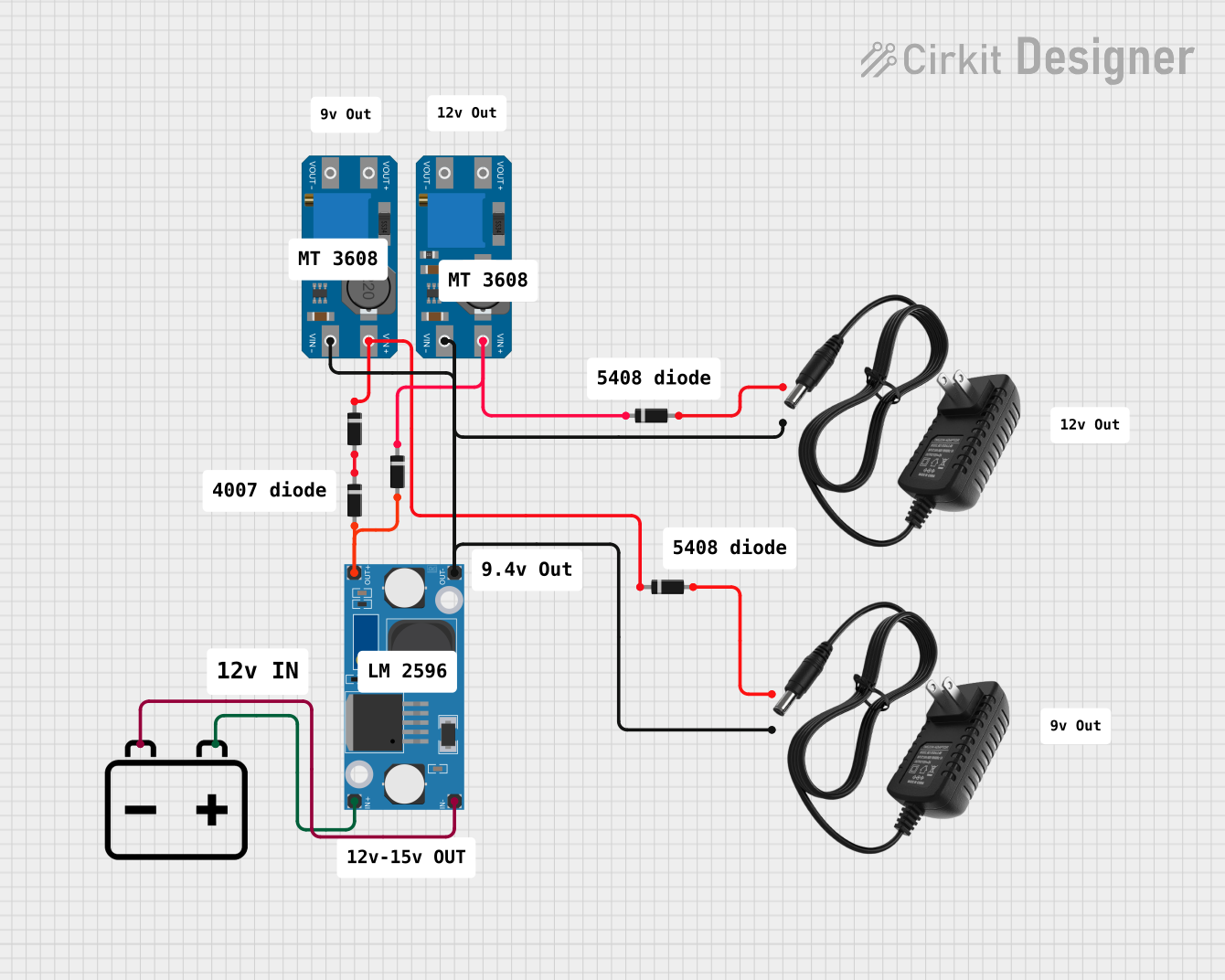
Circuit Documentation
Summary
The circuit in question appears to be a power regulation system that utilizes a combination of step-up and step-down voltage regulators to manage power distribution. The circuit includes two types of voltage regulators, the MT3608 step-up boost converter and the LM2596 step-down buck converter. Additionally, there are multiple diodes in the circuit, likely used for directional current control or voltage drop purposes. The circuit also includes a 12v battery and two 12v power supplies, which are presumably the primary power sources for the circuit.
Component List
MT3608 (Step-Up Boost Converter)
- Description: A boost converter module that steps up voltage from its input (VIN) to its output (VOUT).
- Pins: VOUT+, VIN+, VOUT-, VIN-
LM2596 (Step-Down Buck Converter)
- Description: A buck converter module that steps down voltage from its input (IN) to its output (OUT).
- Pins: OUT-, OUT+, IN-, IN+
Diode
- Description: A semiconductor device that allows current to flow in one direction only.
- Pins: cathode, anode
12v Battery
- Description: A 12-volt battery that provides DC power.
- Pins: +, -
12v Power Supply
- Description: A power supply unit that provides a 12-volt output.
- Pins: +, -
Wiring Details
MT3608 (Step-Up Boost Converter)
- VIN-: Connected to the negative output of the LM2596 and the negative terminals of both 12v power supplies.
- VIN+: Connected to the cathodes of diodes, which are connected to the positive terminals of the 12v power supplies.
- VOUT-: Not connected in the provided net list.
- VOUT+: Not connected in the provided net list.
LM2596 (Step-Down Buck Converter)
- IN-: Connected to the negative terminal of the 12v battery.
- IN+: Connected to the positive terminal of the 12v battery.
- OUT-: Connected to the negative input of the MT3608 and the negative terminals of both 12v power supplies.
- OUT+: Connected to the anodes of diodes.
Diode
- Anode: Connected to the positive output of the LM2596.
- Cathode: Connected to the positive input of the MT3608 and the positive terminals of the 12v power supplies.
12v Battery
- +: Connected to the positive input of the LM2596.
- -: Connected to the negative input of the LM2596.
12v Power Supply
- +: Connected to the anodes of diodes.
- -: Connected to the negative input of the MT3608.
Documented Code
There is no embedded code provided for any microcontrollers in the circuit. If there are microcontrollers or programmable components involved in this circuit, their code is not included in the provided inputs. Therefore, this section cannot be documented at this time.