
Circuit Documentation
Summary of the Circuit
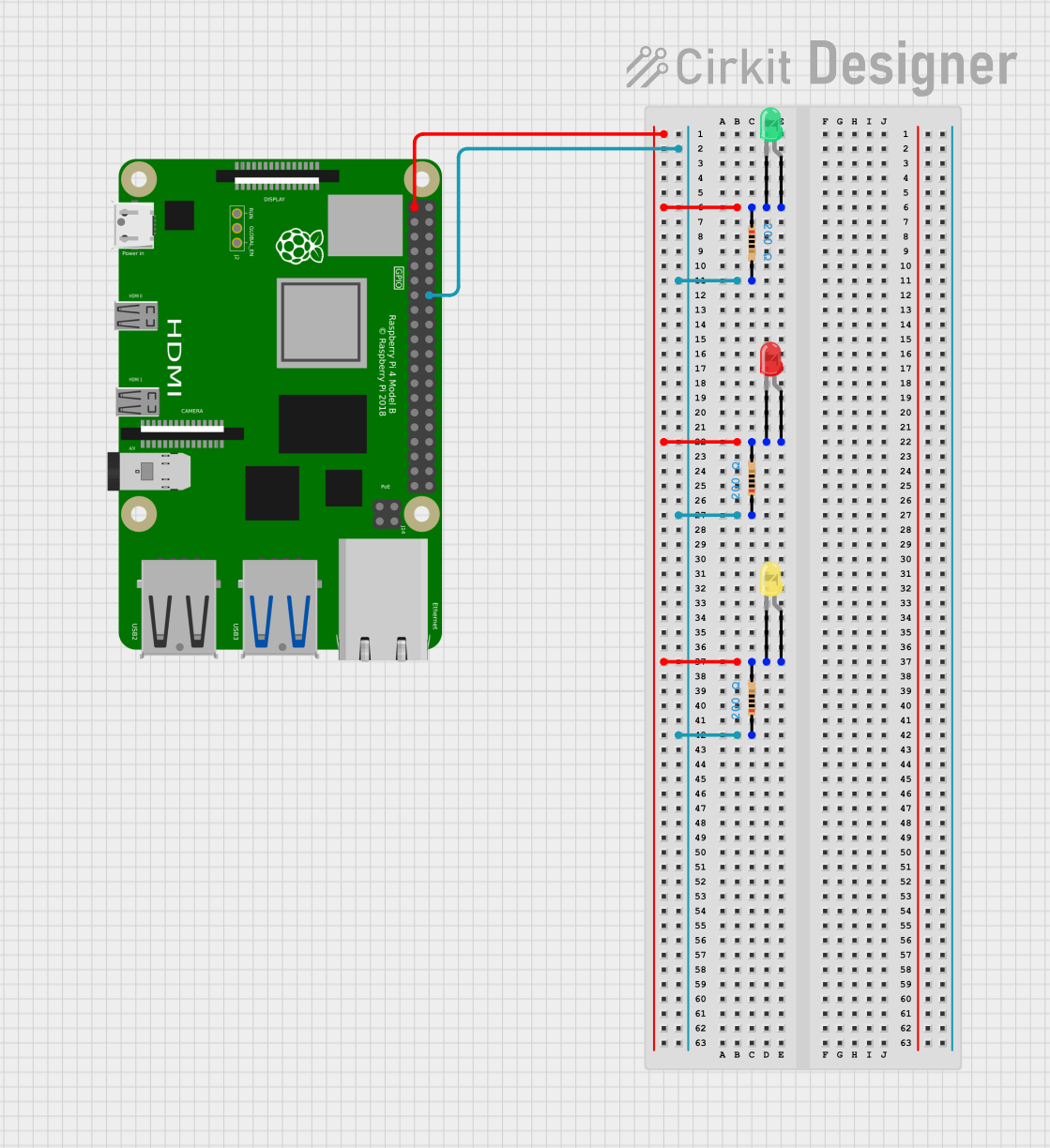
This circuit is designed to interface with a Raspberry Pi 4B and includes three LEDs of different colors (green, yellow, and red) each with a corresponding resistor. The LEDs are powered by the 3.3V power supply from the Raspberry Pi and are grounded through individual resistors to limit the current and protect the LEDs. The circuit does not include any microcontroller code as none was provided.
Component List
Raspberry Pi 4B
- Description: A powerful microcomputer with multiple GPIO pins.
- Purpose: Acts as the central control unit for the circuit, providing power and potential GPIO control for the LEDs.
LED: Two Pin (green)
- Description: A green-colored LED with two pins, anode and cathode.
- Purpose: To emit green light when powered.
LED: Two Pin (yellow)
- Description: A yellow-colored LED with two pins, anode and cathode.
- Purpose: To emit yellow light when powered.
LED: Two Pin (red)
- Description: A red-colored LED with two pins, anode and cathode.
- Purpose: To emit red light when powered.
Resistor (200 Ohms)
- Description: A resistor with a resistance value of 200 Ohms.
- Purpose: To limit the current flowing through the LEDs, protecting them from excessive current.
Wiring Details
Raspberry Pi 4B
- 3V3: Provides power to the anode of the green LED through a resistor.
- GND: Connected to the ground side of the resistors for each LED.
LED: Two Pin (green)
- Cathode: Connected to the 3V3 power supply from the Raspberry Pi through a 200 Ohm resistor.
- Anode: Connected to the ground (GND) through its corresponding resistor.
LED: Two Pin (yellow)
- Cathode: Connected to the 3V3 power supply from the Raspberry Pi through a 200 Ohm resistor.
- Anode: Connected to the ground (GND) through its corresponding resistor.
LED: Two Pin (red)
- Cathode: Connected to the 3V3 power supply from the Raspberry Pi through a 200 Ohm resistor.
- Anode: Connected to the ground (GND) through its corresponding resistor.
Resistor (200 Ohms)
- Pin1: Connected to the 3V3 power supply from the Raspberry Pi.
- Pin2: Connected to the cathode of the corresponding LED and to the GND of the Raspberry Pi.
Documented Code
No code was provided for the microcontrollers in the circuit. If code is later added to control the LEDs via the GPIO pins of the Raspberry Pi, it should be documented in this section.