
Arduino UNO and RFM95 LoRa Transceiver with Inductor for Wireless Communication
View and Edit Project In Cirkit Designer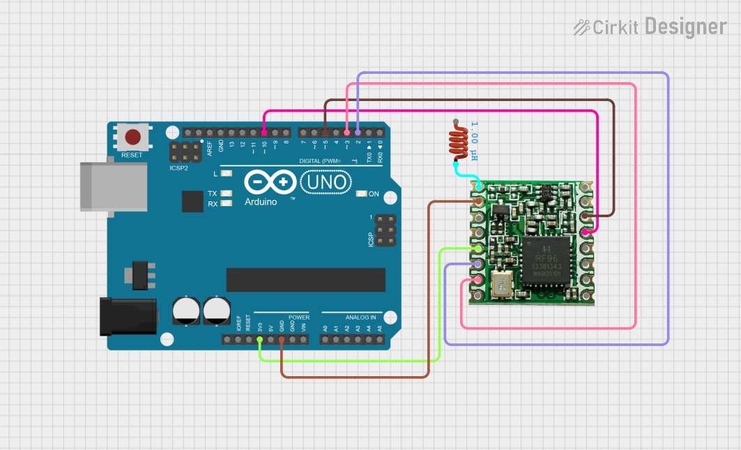
Circuit Documentation
Summary
This document provides a detailed overview of a circuit that integrates an Arduino UNO microcontroller, an RFM95 LoRa module, and an inductor. The Arduino UNO serves as the main controller, interfacing with the RFM95 module for wireless communication. The inductor is connected to the antenna pin of the RFM95 module.
Component List
Arduino UNO
- Description: A microcontroller board based on the ATmega328P.
- Pins: UNUSED, IOREF, Reset, 3.3V, 5V, GND, Vin, A0, A1, A2, A3, A4, A5, SCL, SDA, AREF, D13, D12, D11, D10, D9, D8, D7, D6, D5, D4, D3, D2, D1, D0
RFM95
- Description: A LoRa transceiver module for long-range communication.
- Pins: DIO2, DIO1, DIO0, 3.3V, DIO4, DIO3, GND, ANT, MISO, MOSI, SCK, NSS, RESET, DIO5
Inductor
- Description: An inductor with a value of 1 µH.
- Pins: pin 0, pin 1
- Properties:
- Inductance: 1 µH
Wiring Details
Arduino UNO
- 3.3V: Connected to RFM95 3.3V
- GND: Connected to RFM95 GND
- D10: Connected to RFM95 NSS
- D5: Connected to RFM95 RESET
- D3: Connected to RFM95 DIO1
- D2: Connected to RFM95 DIO0
RFM95
- 3.3V: Connected to Arduino UNO 3.3V
- GND: Connected to Arduino UNO GND
- NSS: Connected to Arduino UNO D10
- RESET: Connected to Arduino UNO D5
- DIO1: Connected to Arduino UNO D3
- DIO0: Connected to Arduino UNO D2
- ANT: Connected to Inductor pin 1
Inductor
- pin 1: Connected to RFM95 ANT
Code Documentation
Arduino UNO Code
void setup() {
  // put your setup code here, to run once:

}

void loop() {
  // put your main code here, to run repeatedly:

}
This code is a basic template for the Arduino UNO. The setup() function is where you initialize your components and configurations, and the loop() function is where the main logic of your program runs repeatedly.
Additional Documentation
This section is reserved for any additional documentation or notes related to the circuit and its operation.