Wi-Fi Controlled ESP32-Based Solenoid Door Lock
Circuit Documentation
Summary
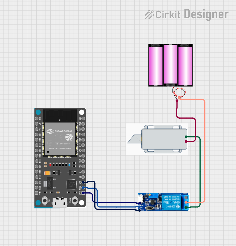
The circuit described in the provided information is designed to control a 12V solenoid lock using an ESP32 Devkit V1 microcontroller. The ESP32 is programmed to connect to a Wi-Fi network and host a web server that listens for an unlock command. Upon receiving the command, the ESP32 triggers a relay module to switch the solenoid lock from a locked to an unlocked state for a duration of 5 seconds before returning it to the locked state. The relay module is powered by the 3.3V output from the ESP32 and controls the higher voltage required by the solenoid lock using a separate 12V battery.
Component List
12V Solenoid Lock
- Description: An electromechanical lock that can be actuated using a 12V power supply.
- Pins:
[-, +] - Purpose: To lock or unlock when energized by the relay module.
Battery 12V
- Description: A 12V power source for the solenoid lock.
- Pins:
[+, -] - Purpose: To provide power to the solenoid lock.
Relay Module 5V-30V
- Description: An electronic switch that allows a low voltage signal to control a higher power circuit.
- Pins:
[common contact, normally open, normally closed, trigger, V-, V+] - Purpose: To control the solenoid lock using a signal from the ESP32.
ESP32 Devkit V1
- Description: A microcontroller with Wi-Fi capability.
- Pins:
[3V3, GND, D15, D2, D4, RX2, TX2, D5, D18, D19, D21, RX0, TX0, D22, D23, EN, VP, VN, D34, D35, D32, D33, D25, D26, D27, D14, D12, D13, VIN] - Purpose: To control the relay module and host a web server for remote unlocking.
Wiring Details
12V Solenoid Lock
- Negative (-) Pin: Connected to the negative (-) terminal of the battery 12V.
- Positive (+) Pin: Connected to the normally open pin of the Relay module 5V-30V.
Battery 12V
- Positive (+) Pin: Connected to the common contact pin of the Relay module 5V-30V.
- Negative (-) Pin: Connected to the negative (-) pin of the 12V Solenoid Lock.
Relay Module 5V-30V
- V+ Pin: Connected to the 3V3 pin of the ESP32 Devkit V1.
- V- Pin: Connected to the GND pin of the ESP32 Devkit V1.
- Trigger Pin: Connected to the D15 pin of the ESP32 Devkit V1.
- Common Contact Pin: Connected to the positive (+) terminal of the battery 12V.
- Normally Open Pin: Connected to the positive (+) pin of the 12V Solenoid Lock.
ESP32 Devkit V1
- 3V3 Pin: Connected to the V+ pin of the Relay module 5V-30V.
- GND Pin: Connected to the V- pin of the Relay module 5V-30V.
- D15 Pin: Connected to the trigger pin of the Relay module 5V-30V.
Documented Code
#include <WiFi.h>
#include <WebServer.h>

const char* ssid = "your_SSID";
const char* password = "your_PASSWORD";

WebServer server(80);

// Define GPIO pin for the relay
const int relayPin = 15;

void setup() {
  Serial.begin(115200);
  pinMode(relayPin, OUTPUT);
  digitalWrite(relayPin, HIGH);  // Lock is initially locked

  // Connect to Wi-Fi
  WiFi.begin(ssid, password);
  while (WiFi.status() != WL_CONNECTED) {
    delay(1000);
    Serial.println("Connecting to WiFi...");
  }

  Serial.println("Connected to WiFi");

  // Setup server routes
  server.on("/unlock", handleUnlock);
  server.begin();
  Serial.println("HTTP server started");
}

void handleUnlock() {
  digitalWrite(relayPin, LOW);  // Unlock the door
  delay(5000);  // Keep it unlocked for 5 seconds
  digitalWrite(relayPin, HIGH); // Lock again
  server.send(200, "text/plain", "Door unlocked");
}

void loop() {
  server.handleClient();
}
Filename: sketch.ino
Description: This code sets up the ESP32 to connect to a Wi-Fi network and start a web server. It listens for an /unlock route to trigger the relay and unlock the solenoid lock for 5 seconds. The relay is controlled by the GPIO pin D15 on the ESP32.