
Circuit Documentation
Summary
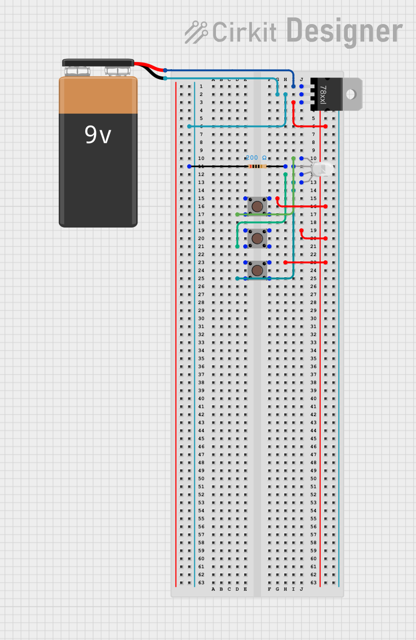
The circuit in question is designed to control an RGB LED using three pushbuttons. Each button corresponds to one color channel of the LED (Red, Green, and Blue). The circuit is powered by a 9V battery, which is regulated down to a lower voltage suitable for the RGB LED and the pushbuttons. A resistor is used in series with the LED to limit the current through it.
Component List
9V Battery
- Description: A standard 9V battery providing the power source for the circuit.
RGB LED (Wokwi compatible)
- Description: A four-pin RGB LED with one common pin and three separate pins for the red, green, and blue channels.
Resistor
- Description: A resistor with a resistance value of 200 Ohms, used to limit the current through the RGB LED.
Pushbutton (x3)
- Description: Three pushbuttons used to control the individual color channels of the RGB LED.
Voltage Regulator
- Description: A voltage regulator used to step down the voltage from the 9V battery to a lower voltage suitable for the RGB LED and pushbuttons.
Wiring Details
9V Battery
- Positive terminal connected to the input pin of the Voltage Regulator.
- Negative terminal connected to the ground pin of the Voltage Regulator and one pin of the Resistor.
RGB LED (Wokwi compatible)
- Red channel pin connected to the output pin of Pushbutton 1.
- Green channel pin connected to the output pin of Pushbutton 2.
- Blue channel pin connected to the output pin of Pushbutton 3.
- Common pin connected to the other pin of the Resistor.
Resistor
- One pin connected to the common pin of the RGB LED.
- The other pin connected to the ground net, which includes the negative terminal of the 9V Battery.
Pushbutton 1
- Input pin connected to the output pin of the Voltage Regulator.
- Output pin connected to the red channel pin of the RGB LED.
Pushbutton 2
- Input pin connected to the output pin of the Voltage Regulator.
- Output pin connected to the green channel pin of the RGB LED.
Pushbutton 3
- Input pin connected to the output pin of the Voltage Regulator.
- Output pin connected to the blue channel pin of the RGB LED.
Voltage Regulator
- Input pin connected to the positive terminal of the 9V Battery.
- Ground pin connected to the negative terminal of the 9V Battery and one pin of the Resistor.
- Output pin connected to the input pins of all three Pushbuttons.
Documented Code
There is no microcontroller code provided for this circuit. The operation of the RGB LED is controlled purely through the mechanical action of the pushbuttons. Each pushbutton acts as a switch to complete the circuit for its respective color channel on the RGB LED.