
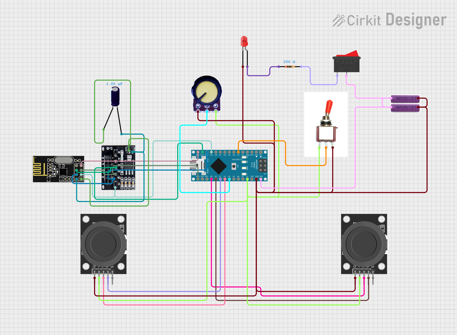
Circuit Documentation
Summary
This circuit is designed to function as a 6-channel transmitter, primarily intended for remote control applications. It utilizes an Arduino Nano as the central microcontroller to process input signals from a potentiometer and two KY-023 Dual Axis Joystick Modules. These inputs are then transmitted wirelessly via an NRF24L01 module, with an NRF24L01 Adapter and an Electrolytic Capacitor to stabilize the power supply to the NRF24L01. A toggle switch is used to control the power flow, and a rocker switch is connected to an LED through a resistor to indicate the power status. The entire circuit is powered by two 3.7V batteries connected in parallel.
Component List
- Arduino Nano: A compact microcontroller board based on the ATmega328P, featuring digital and analog I/O pins.
- NRF24L01: A 2.4GHz wireless transceiver module for wireless communication.
- NRF24L01 Adapter: An adapter module for NRF24L01 to facilitate power stabilization and breakout pins.
- Electrolytic Capacitor: A capacitor used to filter out voltage spikes and smooth the power supply to the NRF24L01.
- Potentiometer: A variable resistor with three terminals, used to provide analog input to the Arduino Nano.
- KY-023 Dual Axis Joystick Module: A joystick module that provides two analog outputs (one for each axis) and a digital output for the joystick switch.
- Toggle Switch: A switch used to control the power flow to the circuit.
- 3.7V Battery: The power source for the circuit.
- Rocker Switch: A switch used to control the power status indicator LED.
- LED (Red): A light-emitting diode used as a power status indicator.
- Resistor: A resistor used to limit the current through the LED.
Wiring Details
Arduino Nano
- D3: Connected to the Toggle Switch (Signal)
- D9: Connected to the NRF24L01 (CE)
- D10: Connected to the NRF24L01 (CSN)
- D11/MOSI: Connected to the NRF24L01 (MOSI)
- D12/MISO: Connected to the NRF24L01 (MISO)
- D13/SCK: Connected to the NRF24L01 (SCK)
- VIN: Connected to the 3.7V Batteries (+)
- GND: Common ground with other components
- 5V: Connected to the KY-023 Joystick Modules (+5V) and the Potentiometer (VCC)
- A0: Connected to the KY-023 Joystick Module (VRx)
- A1: Connected to the KY-023 Joystick Module (VRy)
- A2: Connected to the KY-023 Joystick Module (VRy)
- A3: Connected to the KY-023 Joystick Module (VRx)
- A4: Connected to the Potentiometer (Output)
NRF24L01 and Adapter
- CE: Connected to the Arduino Nano (D9)
- CSN: Connected to the Arduino Nano (D10)
- SCK: Connected to the Arduino Nano (D13/SCK)
- MOSI: Connected to the Arduino Nano (D11/MOSI)
- MISO: Connected to the Arduino Nano (D12/MISO)
- VCC (3V): Connected to the Electrolytic Capacitor (+)
- GND: Connected to the Electrolytic Capacitor (-)
Electrolytic Capacitor
- +: Connected to the NRF24L01 Adapter (VCC)
- -: Connected to the NRF24L01 Adapter (GND)
Potentiometer
- GND: Common ground
- Output: Connected to the Arduino Nano (A4)
- VCC: Connected to the Arduino Nano (5V)
KY-023 Dual Axis Joystick Modules
- GND: Common ground
- +5V: Connected to the Arduino Nano (5V)
- VRx: Connected to the Arduino Nano (A0, A3)
- VRy: Connected to the Arduino Nano (A1, A2)
- SW: Not connected
Toggle Switch
- Vcc: Connected to the Arduino Nano (5V)
- Sig: Connected to the Arduino Nano (D3)
- Gnd: Common ground
3.7V Batteries
- +: Connected to the Arduino Nano (VIN) and Rocker Switch (2)
- -: Common ground
Rocker Switch
- 1: Connected to the Resistor (pin2)
- 2: Connected to the 3.7V Batteries (+)
LED (Red)
- Cathode: Common ground
- Anode: Connected to the Resistor (pin1)
Resistor
- Pin1: Connected to the LED (Anode)
- Pin2: Connected to the Rocker Switch (1)
Documented Code
// 6 Channel Transmitter
// Tutorial Video https://youtu.be/731I4PEUxWU

#include <SPI.h>
#include <nRF24L01.h>
#include <RF24.h>
const uint64_t pipeOut = 0xE9E8F0F0E1LL;   //IMPORTANT: The same as in the receiver 0xE9E8F0F0E1LL
RF24 radio(9, 10); // select CE,CSN pin
struct Signal {
  byte throttle;
  byte pitch;
  byte roll;
  byte yaw;
  byte aux1;
  byte aux2;
};
Signal data;
void ResetData()
{
  data.throttle = 12;   // Motor stop (Signal lost position)
  data.pitch = 127;     // Center (Signal lost position)
  data.roll = 127;      // Center (Signal lost position)
  data.yaw = 127;       // Center (Signal lost position)
  data.aux1 = 127;      // Center (Signal lost position)
  data.aux2 = 127;      // Center (Signal lost position)
}
void setup()
{
  radio.begin();
  radio.openWritingPipe(pipeOut);
  radio.setAutoAck(false);
  radio.setDataRate(RF24_250KBPS);
  radio.setPALevel(RF24_PA_HIGH);
  radio.stopListening();
  ResetData();

}
int mapJoystickValues(int val, int lower, int middle, int upper, bool reverse)
{
  val = constrain(val, lower, upper);
  if ( val < middle )
  val = map(val, lower, middle, 0, 128);
  else
  val = map(val, middle, upper, 128, 255);
  return ( reverse ? 255 - val : val );
}
void loop()
{
  // Control Stick Calibration
  // Setting may be required for the correct values of the control levers
  data.throttle = mapJoystickValues( analogRead(A0), 12, 524, 1020, true );   // "true" or "false" for signal direction
  data.roll = mapJoystickValues( analogRead(A3), 12, 524, 1020, true );       // "true" or "false" for servo direction
  data.pitch = mapJoystickValues( analogRead(A2), 12, 524, 1020, false );     // "true" or "false" for servo direction
  data.yaw = mapJoystickValues( analogRead(A1), 12, 524, 1020, false );       // "true" or "false" for servo direction

  data.aux1 = mapJoystickValues( analogRead(A6), 12, 524, 1020, true );       // "true" or "false" for servo direction
  data.aux2 = mapJoystickValues( analogRead(A7), 12, 524, 1020, true );       // "true" or "false" for servo direction
  radio.write(&data, sizeof(Signal));
}
This code is responsible for reading the analog values from the potentiometer and joystick modules, mapping these values to a range suitable for radio transmission, and sending the structured data wirelessly using the NRF24L01 module. The ResetData function initializes the control signals to their neutral or 'signal lost' positions. The mapJoystickValues function is used to map the raw analog readings to a standardized range, with optional reversal of the signal direction. The loop function continuously reads the joystick and potentiometer values, maps them, and transmits the data.