Battery-Powered Buzzer Circuit

Circuit Documentation
Summary of the Circuit
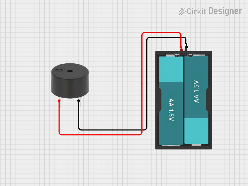
The circuit described by the provided inputs is a simple buzzer circuit powered by a 3V battery source. The circuit consists of two main components: a buzzer and a battery pack that holds two AA batteries. The buzzer is directly connected to the battery pack, with the positive terminal of the battery connected to the buzzer's power input and the ground terminal connected to the buzzer's ground. There is no microcontroller or additional control logic involved in this circuit, indicating that the buzzer will be continuously powered and active as long as the battery is connected.
Component List
Buzzer
- Description: An electromechanical component that emits sound when powered.
- Purpose: To generate an audible alert or tone when powered by the battery.
- Pins:
- PIN (Power Input)
- GND (Ground)
Battery AAx2 3V
- Description: A battery pack holding two AA batteries to provide a 3V power source.
- Purpose: To supply electrical power to the buzzer.
- Pins:
- VCC (Positive Voltage)
- GND (Ground)
Wiring Details
Buzzer
- PIN (Power Input): Connected to the VCC of the Battery AAx2 3V.
- GND (Ground): Connected to the GND of the Battery AAx2 3V.
Battery AAx2 3V
- VCC (Positive Voltage): Connected to the PIN of the Buzzer.
- GND (Ground): Connected to the GND of the Buzzer.
Documented Code
There is no embedded code provided for this circuit as it does not include any programmable components or microcontrollers. The operation of the circuit is purely electrical, with the buzzer being activated directly by the battery power.