
Circuit Documentation
Summary
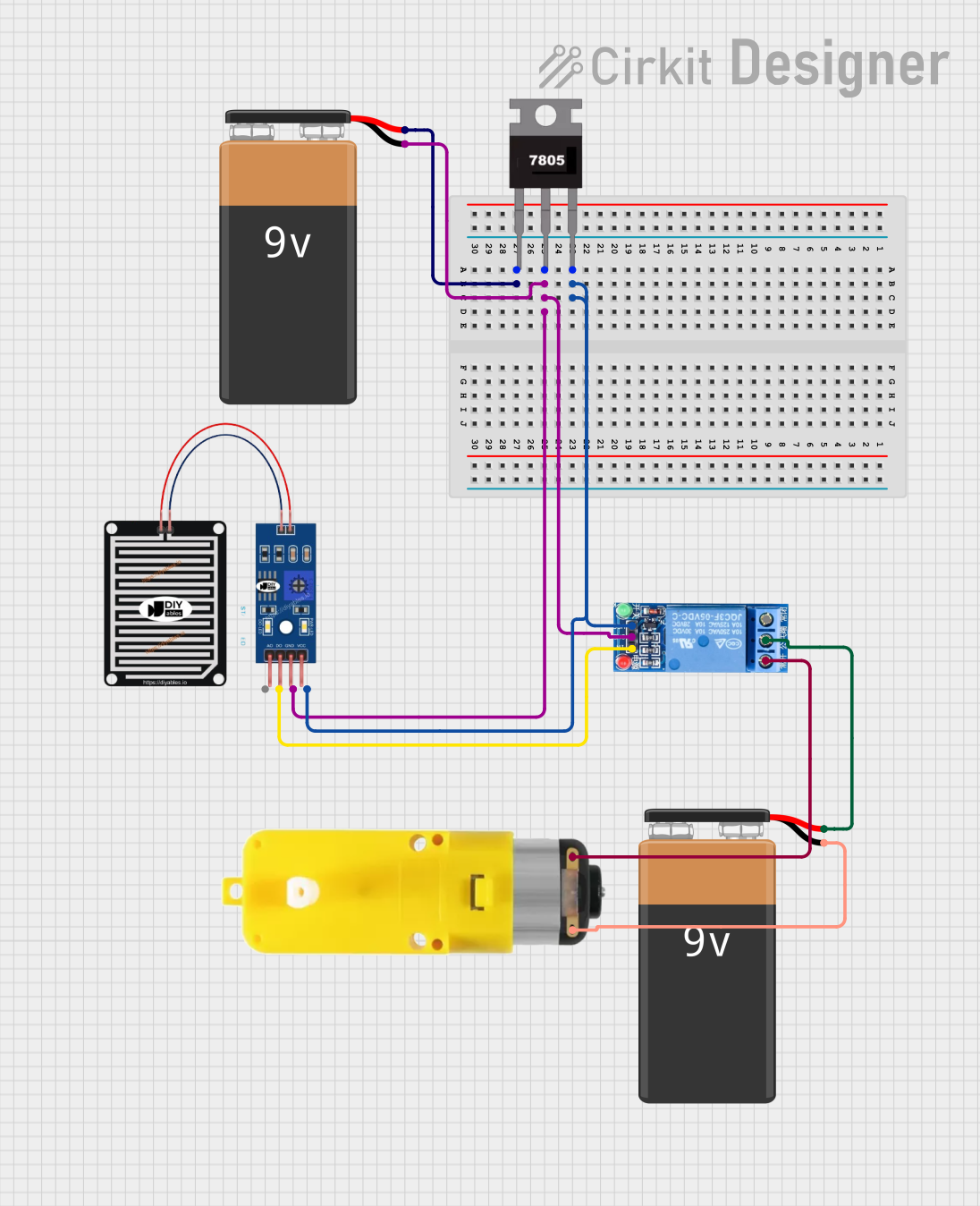
This circuit is designed to control a motor using a rain sensor and a relay. The circuit includes a 7805 voltage regulator to provide a stable 5V supply to the rain sensor and relay. The motor is powered by a separate 9V battery and is controlled by the relay based on the rain sensor's output.
Component List
7805 Voltage Regulator
- Description: A linear voltage regulator that outputs a stable 5V.
- Pins: Vin, Gnd, Vout
9V Battery (Primary)
- Description: Provides the primary power supply for the circuit.
- Pins: -, +
Rain Sensor
- Description: Detects the presence of rain and outputs a digital signal.
- Pins: AO, DO, GRD, VCC
1 Channel Relay 5V
- Description: A relay module that can be triggered by a 5V signal to control higher power devices.
- Pins: VCC, GND, IN, NC, COM, NO
Motor with Reducer
- Description: A motor with a gear reducer to control speed and torque.
- Pins: 3 - 6 VCC, GND
9V Battery (Secondary)
- Description: Provides power to the motor.
- Pins: -, +
Wiring Details
7805 Voltage Regulator
- Vin: Connected to the + pin of the primary 9V Battery.
- Gnd: Connected to the - pin of the primary 9V Battery, the GRD pin of the Rain Sensor, and the GND pin of the 1 Channel Relay 5V.
- Vout: Connected to the VCC pin of the Rain Sensor and the VCC pin of the 1 Channel Relay 5V.
9V Battery (Primary)
- +: Connected to the Vin pin of the 7805 Voltage Regulator.
- -: Connected to the Gnd pin of the 7805 Voltage Regulator, the GRD pin of the Rain Sensor, and the GND pin of the 1 Channel Relay 5V.
Rain Sensor
- AO: Not connected.
- DO: Connected to the IN pin of the 1 Channel Relay 5V.
- GRD: Connected to the Gnd pin of the 7805 Voltage Regulator and the - pin of the primary 9V Battery.
- VCC: Connected to the Vout pin of the 7805 Voltage Regulator.
1 Channel Relay 5V
- VCC: Connected to the Vout pin of the 7805 Voltage Regulator.
- GND: Connected to the Gnd pin of the 7805 Voltage Regulator and the - pin of the primary 9V Battery.
- IN: Connected to the DO pin of the Rain Sensor.
- NC: Connected to the 3 - 6 VCC pin of the Motor with Reducer.
- COM: Connected to the + pin of the secondary 9V Battery.
- NO: Not connected.
Motor with Reducer
- 3 - 6 VCC: Connected to the NC pin of the 1 Channel Relay 5V.
- GND: Connected to the - pin of the secondary 9V Battery.
9V Battery (Secondary)
- +: Connected to the COM pin of the 1 Channel Relay 5V.
- -: Connected to the GND pin of the Motor with Reducer.
Code
No microcontroller code is provided for this circuit.