Arduino UNO Light Sensor Circuit
Circuit Documentation
Summary of the Circuit
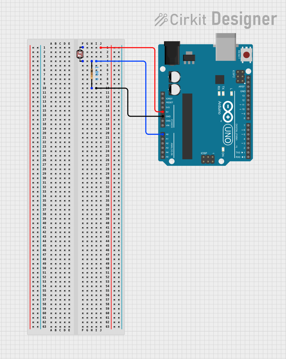
This circuit consists of an Arduino UNO microcontroller, a photocell (Light Dependent Resistor, LDR), and a resistor. The purpose of the circuit is to measure the light intensity using the photocell and provide an analog input to the Arduino UNO for further processing. The resistor is used to create a voltage divider with the photocell, which allows the Arduino to measure changes in resistance due to changes in light levels.
Component List
Arduino UNO
- Description: A microcontroller board based on the ATmega328P.
- Pins Used: 5V, GND, A0.
- Purpose: Acts as the central processing unit of the circuit, reading the analog voltage from the photocell and executing the embedded code.
Photocell (LDR)
- Description: A light-sensitive device whose resistance changes with light intensity.
- Pins Used: pin 0, pin 1.
- Purpose: Senses the ambient light level to provide an analog signal to the Arduino.
Resistor
- Description: A passive two-terminal electrical component that implements electrical resistance as a circuit element.
- Value: 1 Ohm.
- Pins Used: pin1, pin2.
- Purpose: Forms a voltage divider with the photocell to provide an analog input to the Arduino.
Wiring Details
Arduino UNO
- 5V: Connected to pin 1 of the Photocell (LDR).
- GND: Connected to pin2 of the Resistor.
- A0: Connected to pin 0 of the Photocell (LDR) and pin1 of the Resistor.
Photocell (LDR)
- pin 0: Connected to pin1 of the Resistor and A0 on the Arduino UNO.
- pin 1: Connected to the 5V pin on the Arduino UNO.
Resistor
- pin1: Connected to pin 0 of the Photocell (LDR) and A0 on the Arduino UNO.
- pin2: Connected to the GND pin on the Arduino UNO.
Documented Code
Arduino UNO Code (sketch.ino)
void setup() {
  // put your setup code here, to run once:

}

void loop() {
  // put your main code here, to run repeatedly:

}
The provided code is a template with empty setup() and loop() functions. The setup() function is intended to contain initialization code that runs once when the microcontroller is powered on or reset. The loop() function is meant to contain the main logic of the program, which runs repeatedly as long as the microcontroller is powered.
To complete this code, one would typically configure the A0 pin as an input and read its value using analogRead(A0). The read value would then be used to determine the light level sensed by the photocell. This value could be used to trigger events, control outputs, or be sent to a computer for logging or further analysis.