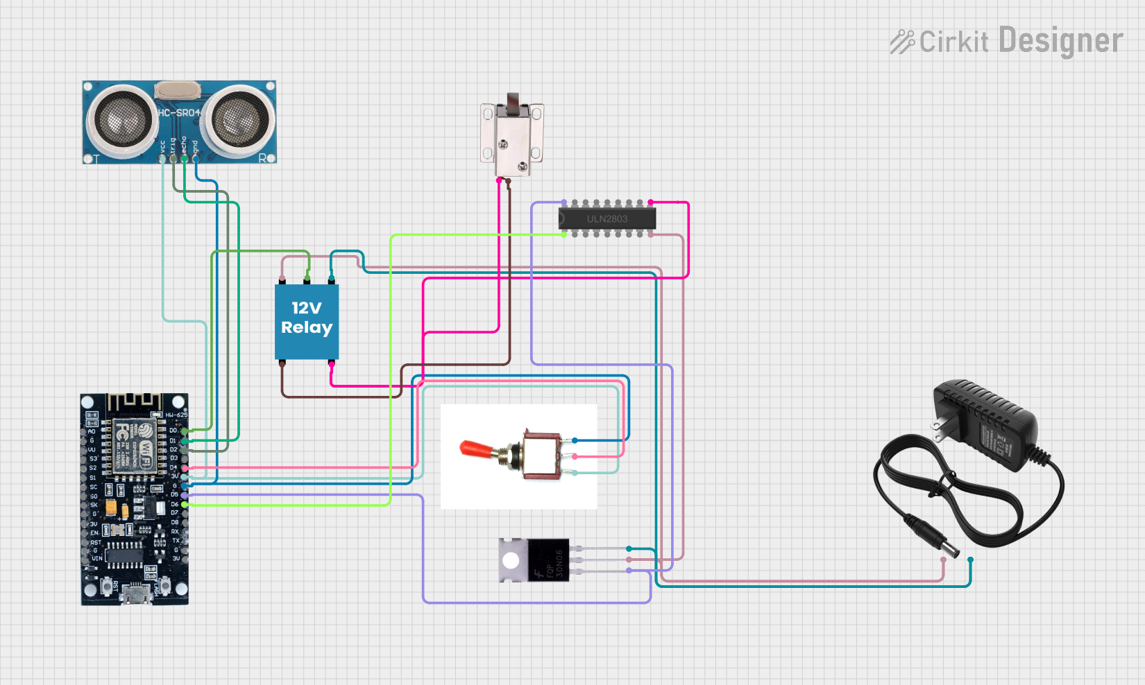
ESP8266-Controlled Solenoid Lock with Ultrasonic Sensor Activation

Circuit Documentation
Summary
This circuit is designed to interface an ESP8266 microcontroller with various components including a Mosfet, a Toggle Switch, an Ultrasonic Sensor, a 12V Relay, a ULN2803 Darlington Array, a 12V power supply, and a 12V solenoid lock. The ESP8266 controls the logic and processing, interfacing with the Ultrasonic Sensor for distance measurement, the Toggle Switch for user input, and the Mosfet for power control. The ULN2803 Darlington Array is used to drive higher current loads, and the 12V Relay is used to switch the 12V solenoid lock. The 12V power supply provides power to the circuit.
Component List
ESP8266
- Microcontroller with WiFi capability.
- Pins: 3V, G, D8, D7, D6, D5, D4, D3, D2, D1, D0, A0, S3, S2, S1, SC, S0, SK, EN, VIN, RST, VU.
Mosfet
- A type of transistor used for switching electronic signals.
- Pins: Gate, Drain, Source.
Toggle Switch
- A switch that has a lever to toggle the device between different states.
- Pins: Vcc, Sig, Gnd.
Ultrasonic Sensor
- A sensor used to measure distance by emitting ultrasonic waves and measuring the time it takes for the echo to return.
- Pins: +VCC, Trigger, Echo, GND.
12V Relay
- An electrically operated switch that allows you to turn on or off a circuit using voltage and/or current much higher than a microcontroller can handle.
- Pins: +, -, C, NC, NO.
12V Power Supply
- Provides a 12V voltage source for the circuit.
- Pins: +, -.
ULN2803 Darlington Array
- An array of Darlington pairs to provide high-current drive capability.
- Pins: I1, I2, I3, I4, I5, I6, I7, I8, O3, O4, O5, O6, O7, O8, GND, COMMON, O1, O2.
12V Solenoid Lock
- An electronic lock that can be controlled via an electrical current.
- Pins: VCC, GND.
Wiring Details
ESP8266
- D6 connected to ULN2803 Darlington Array I1.
- D5 connected to Mosfet Gate and ULN2803 Darlington Array O1.
- G connected to Toggle Switch Gnd and Ultrasonic Sensor GND.
- 3V connected to Toggle Switch Vcc and Ultrasonic Sensor +VCC.
- D4 connected to Toggle Switch Sig.
- D2 connected to Ultrasonic Sensor Trigger.
- D1 connected to Ultrasonic Sensor Echo.
- D0 connected to 12V Relay C.
Mosfet
- Gate connected to ESP8266 D5 and ULN2803 Darlington Array O1.
- Drain connected to 12V power supply +, ULN2803 Darlington Array GND, and 12V Relay +.
- Source connected to 12V power supply - and 12V Relay -.
Toggle Switch
- Vcc connected to ESP8266 3V and Ultrasonic Sensor +VCC.
- Sig connected to ESP8266 D4.
- Gnd connected to ESP8266 G and Ultrasonic Sensor GND.
Ultrasonic Sensor
- +VCC connected to ESP8266 3V and Toggle Switch Vcc.
- Trigger connected to ESP8266 D2.
- Echo connected to ESP8266 D1.
- GND connected to ESP8266 G and Toggle Switch Gnd.
12V Relay
- connected to Mosfet Drain, ULN2803 Darlington Array GND, and 12V power supply +.
- connected to Mosfet Source and 12V power supply -.
- C connected to ESP8266 D0.
- NC connected to 12V solenoid lock GND.
- NO connected to 12V solenoid lock VCC and ULN2803 Darlington Array COMMON.
ULN2803 Darlington Array
- I1 connected to ESP8266 D6.
- O1 connected to Mosfet Gate and ESP8266 D5.
- GND connected to Mosfet Drain and 12V Relay +.
- COMMON connected to 12V solenoid lock VCC and 12V Relay NO.
12V Solenoid Lock
- VCC connected to ULN2803 Darlington Array COMMON and 12V Relay NO.
- GND connected to 12V Relay NC.
Documented Code
Since no code was provided, this section is left blank. When code is available, it should be documented here with explanations of how the code interacts with the hardware components listed above.