Arduino-Controlled Bluetooth Robot with L298N Motor Driver and LED Indicators
Circuit Documentation
Summary
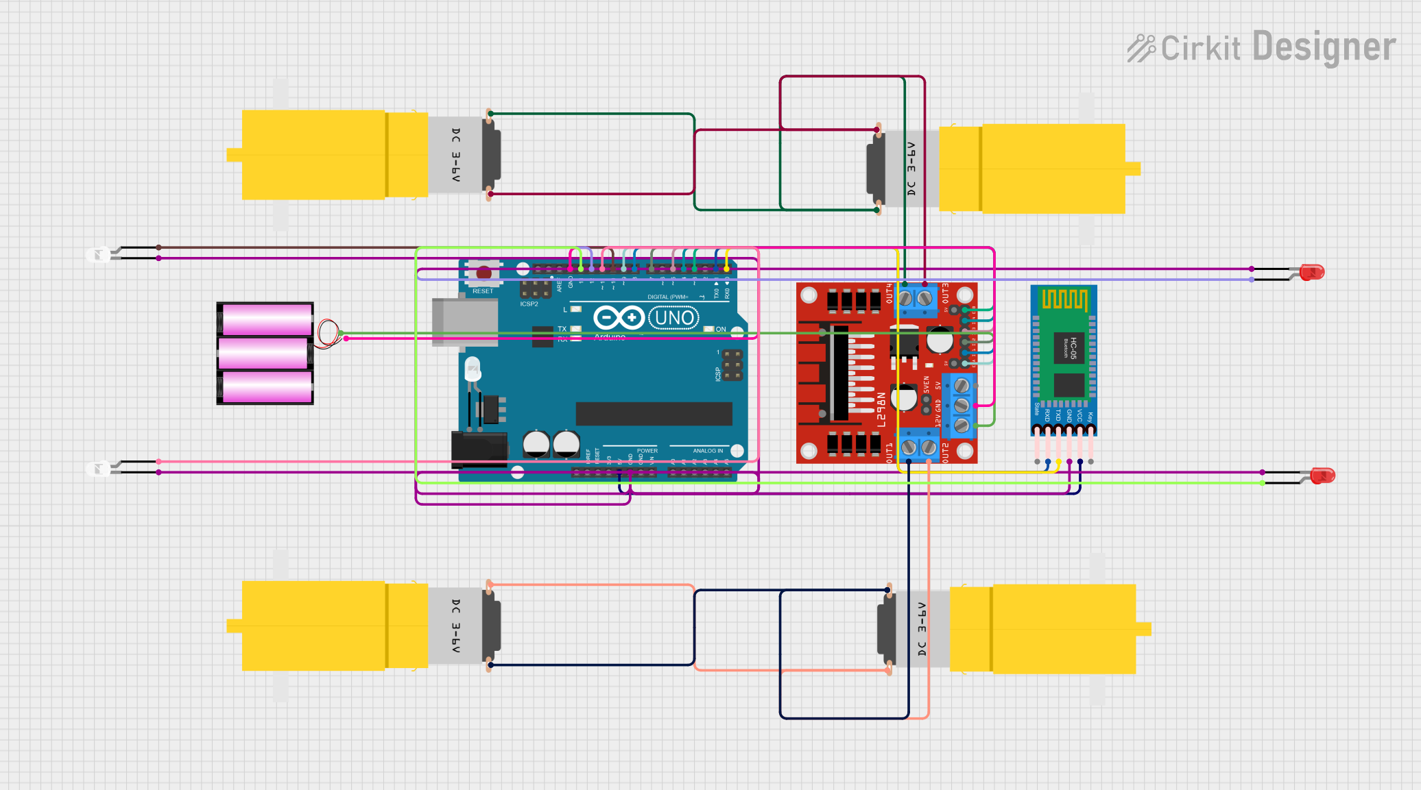
This circuit is designed to control a set of four "Motor amarillo motorreductor hobby" motors using an "Arduino UNO" microcontroller and an "L298N DC motor driver". The circuit also includes an "HC-05 Bluetooth Module" for wireless communication and a set of LEDs for indication purposes. The power is supplied by a "battery 12v". The Arduino UNO is programmed to manage the motor driver, read signals from the Bluetooth module, and control the LEDs.
Component List
Motors
- Motor amarillo motorreductor hobby: A hobbyist DC gear motor that requires a power supply and ground connection.
Microcontroller
- Arduino UNO: A microcontroller board based on the ATmega328P, equipped with a variety of digital and analog I/O pins.
Motor Driver
- L298N DC motor driver: A dual H-bridge motor driver capable of driving two DC motors or one stepper motor.
Bluetooth Module
- HC-05 Bluetooth Module: A wireless communication module that allows for serial communication over Bluetooth.
LEDs
- LED: Two Pin (white): A basic white LED with an anode and cathode for indication.
- LED: Two Pin (red): A basic red LED with an anode and cathode for indication.
Power Supply
- battery 12v: A 12-volt battery providing the main power source for the motor driver and indirectly for other components through voltage regulation.
Wiring Details
Motors
- Motor amarillo motorreductor hobby: Each motor's
vccandGNDpins are connected to the corresponding output pinsOUT1,OUT2,OUT3, andOUT4of the L298N motor driver.
Arduino UNO
- Digital pins
D13,D12,D11, andD10are connected to the anodes of the red and white LEDs. - Digital pins
D9,D8,D7,D5,D4, andD3are connected to theENA,IN1,IN2,IN3,IN4, andENBpins of the L298N motor driver, respectively. - Digital pins
D1andD0are used for serial communication with the HC-05 Bluetooth module'sRXDandTXDpins. - The
5Vpin provides power to the HC-05 Bluetooth module. - The
GNDpin is connected to the common ground net, which includes the cathodes of the LEDs and the ground of the HC-05 Bluetooth module.
L298N DC motor driver
- The
12Vpin is connected to the positive terminal of the 12v battery. - The
GNDpin is connected to the negative terminal of the 12v battery and the common ground net.
HC-05 Bluetooth Module
- The
VCCpin is connected to the5Voutput from the Arduino UNO. - The
GNDpin is connected to the common ground net.
LEDs
- The anodes of the red and white LEDs are connected to their respective Arduino UNO digital pins for control.
- The cathodes of all LEDs are connected to the common ground net.
Documented Code
void setup() {
  // put your setup code here, to run once:

}

void loop() {
  // put your main code here, to run repeatedly:

}
The provided code is a template with empty setup() and loop() functions. The setup() function is intended for initialization code that runs once at startup, and the loop() function contains the main logic of the program that runs repeatedly. Actual implementation details need to be added to control the motors, read from the Bluetooth module, and manage the LEDs.