
Arduino UNO and Nano-Based Wireless Joystick-Controlled Robot with NRF24L01
View and Edit Project In Cirkit Designer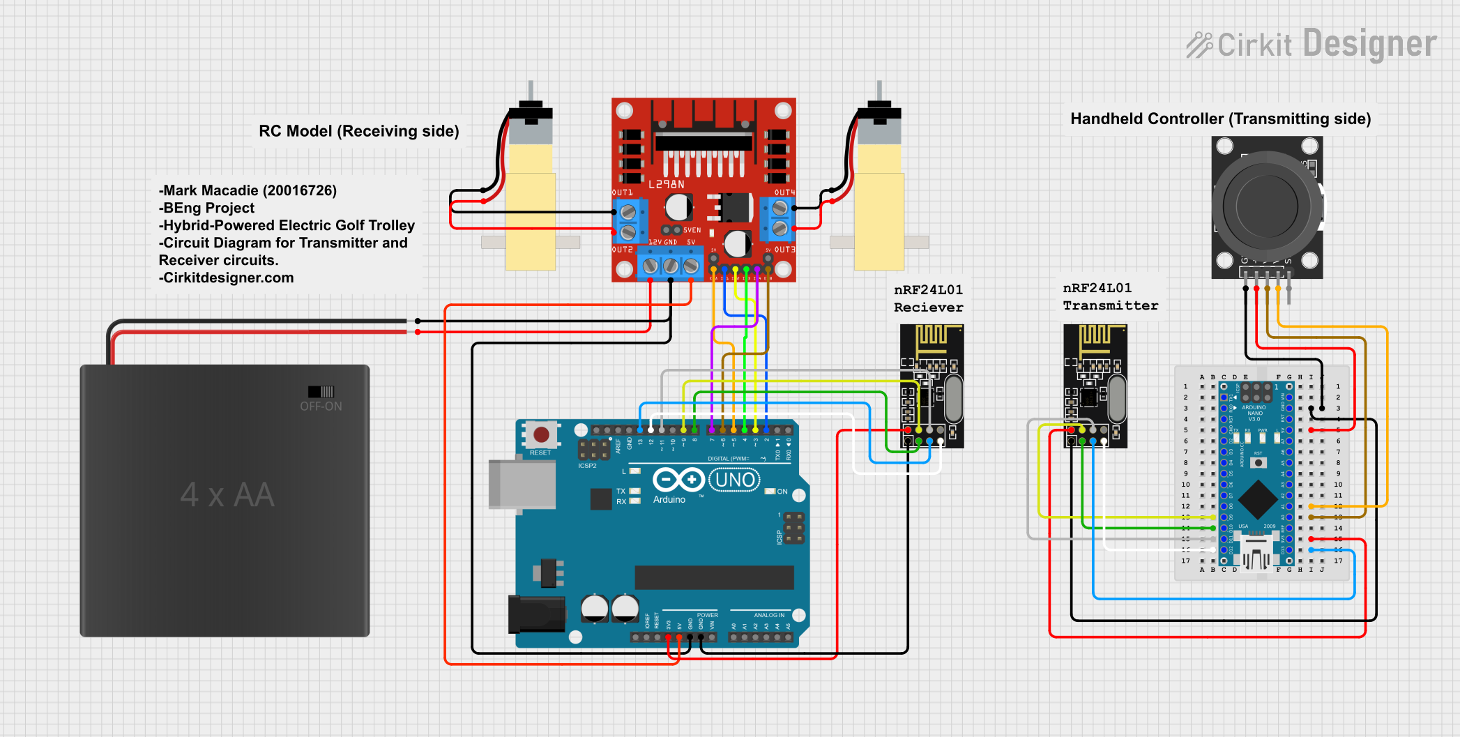
Circuit Documentation
Summary
This circuit is designed to control two hobby gear motors using an Arduino UNO and an L298N motor driver. The control signals for the motors are received wirelessly via an NRF24L01 module, which communicates with another Arduino Nano equipped with a joystick module. The Arduino Nano reads the joystick's position and transmits the data to the Arduino UNO, which then adjusts the motor speeds accordingly.
Component List
Arduino UNO
- Description: A microcontroller board based on the ATmega328P.
- Pins: UNUSED, IOREF, Reset, 3.3V, 5V, GND, Vin, A0, A1, A2, A3, A4, A5, SCL, SDA, AREF, D13, D12, D11, D10, D9, D8, D7, D6, D5, D4, D3, D2, D1, D0
L298N DC Motor Driver
- Description: A dual H-bridge motor driver that allows control of two DC motors.
- Pins: OUT1, OUT2, 12V, GND, 5V, OUT3, OUT4, 5V-ENA-JMP-I, 5V-ENA-JMP-O, +5V-J1, +5V-J2, ENA, IN1, IN2, IN3, IN4, ENB
NRF24L01
- Description: A 2.4GHz wireless transceiver module.
- Pins: IRQ (not used), MOSI, CSN, VCC (3V), GND, CE, SCK, MISO
4xAA Battery Pack
- Description: A battery pack that holds four AA batteries.
- Pins: POS, NEG
Hobby Gearmotor with 48:1 Gearbox
- Description: A small DC motor with a 48:1 gearbox.
- Pins: pin 1, pin 2
KY-023 Dual Axis Joystick Module
- Description: A joystick module with two potentiometers for X and Y axis control.
- Pins: GND, +5V, VRx, VRy, SW
Arduino Nano
- Description: A small, breadboard-friendly microcontroller board based on the ATmega328P.
- Pins: D1/TX, D0/RX, RESET, GND, D2, D3, D4, D5, D6, D7, D8, D9, D10, D11/MOSI, D12/MISO, VIN, 5V, A7, A6, A5, A4, A3, A2, A1, A0, AREF, 3V3, D13/SCK
Wiring Details
Arduino UNO
- 3.3V to NRF24L01 VCC (3V)
- 5V to L298N DC Motor Driver 5V
- GND to 4xAA Battery Pack NEG and L298N DC Motor Driver GND and NRF24L01 GND
- D13 to NRF24L01 SCK
- D12 to NRF24L01 MISO
- D11 to NRF24L01 MOSI
- D9 to NRF24L01 CSN
- D8 to NRF24L01 CE
- D7 to L298N DC Motor Driver IN4
- D6 to L298N DC Motor Driver ENB
- D5 to L298N DC Motor Driver ENA
- D4 to L298N DC Motor Driver IN3
- D3 to L298N DC Motor Driver IN2
- D2 to L298N DC Motor Driver IN1
L298N DC Motor Driver
- OUT1 to Hobby Gearmotor pin 1
- OUT2 to Hobby Gearmotor pin 2
- OUT3 to Hobby Gearmotor pin 2
- OUT4 to Hobby Gearmotor pin 1
- 12V to 4xAA Battery Pack POS
Arduino Nano
- GND to KY-023 Dual Axis Joystick Module GND and NRF24L01 GND
- 5V to KY-023 Dual Axis Joystick Module +5V
- A0 to KY-023 Dual Axis Joystick Module VRx
- A1 to KY-023 Dual Axis Joystick Module VRy
- D9 to NRF24L01 CSN
- D10 to NRF24L01 CE
- D11/MOSI to NRF24L01 MOSI
- 3V3 to NRF24L01 VCC (3V)
- D12/MISO to NRF24L01 MISO
- D13/SCK to NRF24L01 SCK
Code Documentation
Arduino UNO Code
#include <SPI.h>
#include <nRF24L01.h>
#include <RF24.h>

// Use valid PWM pins for enA and enB on Arduino Uno
#define enA 5   // PWM pin
#define in1 2
#define in2 3
#define enB 6   // PWM pin
#define in3 4
#define in4 7

RF24 radio(8, 9); // CE pin = 8, CSN pin = 9
const byte address[6] = "00001"; // RF24 address

// Structure to match what's sent by transmitter
struct {
  int xAxis;
  int yAxis;
} joystickData;

// Motor speed variables
int motorSpeedA = 0;
int motorSpeedB = 0;

void setup() {
  Serial.begin(9600);

  pinMode(enA, OUTPUT);
  pinMode(in1, OUTPUT);
  pinMode(in2, OUTPUT);
  pinMode(enB, OUTPUT);
  pinMode(in3, OUTPUT);
  pinMode(in4, OUTPUT);

  radio.begin();
  radio.openReadingPipe(0, address);
  radio.setPALevel(RF24_PA_MIN);
  radio.startListening(); // Set as receiver
}

void loop() {
  // Check if new data is available
  if (radio.available()) {
    radio.read(&joystickData, sizeof(joystickData));
  }

  int xAxis = joystickData.xAxis;
  int yAxis = joystickData.yAxis;

  // Debug prints
  Serial.print("X: "); Serial.print(xAxis);
  Serial.print(" | Y: "); Serial.println(yAxis);

  // ======= Y-Axis Control (Forward/Backward) =======
  if (yAxis < 470) {
    // Backward
    digitalWrite(in1, HIGH);
    digitalWrite(in2, LOW);
    digitalWrite(in3, HIGH);
    digitalWrite(in4, LOW);
    // Map Y-axis from [470..0] to [0..255]
    motorSpeedA = map(yAxis, 470, 0, 0, 255);
    motorSpeedB = map(yAxis, 470, 0, 0, 255);
  }
  else if (yAxis > 550) {
    // Forward
    digitalWrite(in1, LOW);
    digitalWrite(in2, HIGH);
    digitalWrite(in3, LOW);
    digitalWrite(in4, HIGH);
    // Map Y-axis from [550..1023] to [0..255]
    motorSpeedA = map(yAxis, 550, 1023, 0, 255);
    motorSpeedB = map(yAxis, 550, 1023, 0, 255);
  }
  else {
    // Stop
    motorSpeedA = 0;
    motorSpeedB = 0;
  }

  // ======= X-Axis Control (Left/Right) =======
  if (xAxis < 470) {
    // Move left
    int xMapped = map(xAxis, 470, 0, 0, 255);
    motorSpeedA = motorSpeedA - xMapped; // Decrease left motor speed
    motorSpeedB = motorSpeedB + xMapped; // Increase right motor speed
    // Constrain the range to [0..255]
    if (motorSpeedA < 0)  motorSpeedA = 0;
    if (motorSpeedB > 255) motorSpeedB = 255;
  }
  else if (xAxis > 550) {
    // Move right
    int xMapped = map(xAxis, 550, 1023, 0, 255);
    motorSpeedA = motorSpeedA + xMapped; // Increase left motor speed
    motorSpeedB = motorSpeedB - xMapped; // Decrease right motor speed
    // Constrain the range to [0..255]
    if (motorSpeedA > 255) motorSpeedA = 255;
    if (motorSpeedB <