
Wi-Fi Controlled Smart Lighting System with ESP8266 and Relay Module
View and Edit Project In Cirkit Designer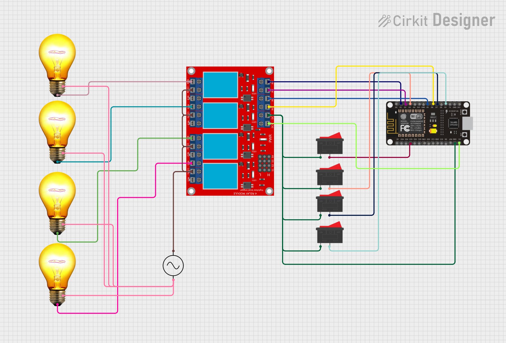
Circuit Documentation
Summary
This circuit is designed to control four AC bulbs using a 4-channel relay module, which is interfaced with an ESP8266 NodeMCU microcontroller. The microcontroller receives commands and controls the state of each relay, which in turn switches the AC bulbs on or off. The circuit also includes rocker switches that provide manual control over the relays. The ESP8266 NodeMCU is programmed to communicate with the Sinric Pro service, allowing for smart home integration.
Component List
4 Channel Relay Module
- Description: A module with 4 relays that can control high power devices.
- Pins: 4 Normally Open (N.O.), 4 Common (COM), 4 Normally Closed (N.C.), Control Pins (IN 1-4), Power Supply Pins (VCC+, VCC-).
Rocker Switch
- Description: A switch that rocks back and forth to open or close the circuit.
- Pins: 2 pins for each switch.
ESP8266 NodeMCU
- Description: A Wi-Fi enabled microcontroller for IoT applications.
- Pins: Digital I/O, Analog Input, Power (3V3, GND, VIN), Communication (RX, TX).
AC Bulb
- Description: A standard AC powered light bulb.
- Pins: Phase (P), Neutral (N).
AC Supply
- Description: Provides AC power to the circuit.
- Pins: Positive (+ve), Negative (-ve).
Wiring Details
4 Channel Relay Module
- N.O. 1-4: Connected to the phase pin of each AC bulb.
- COM 1-4: Interconnected and connected to the positive pin of the AC supply.
- IN 1-4: Controlled by the ESP8266 NodeMCU digital pins (D1, D2, D5, D6).
- VCC+: Connected to the VIN pin of the ESP8266 NodeMCU.
- VCC- (GND): Connected to the ground of the ESP8266 NodeMCU and all rocker switches.
Rocker Switches
- Switch 1: Connected between the ESP8266 NodeMCU D3 pin and ground.
- Switch 2: Connected between the ESP8266 NodeMCU D7 pin and ground.
- Switch 3: Connected between the ESP8266 NodeMCU RX pin and ground.
- Switch 4: Connected between the ESP8266 NodeMCU SD3 pin and ground.
ESP8266 NodeMCU
- VIN: Provides power to the relay module.
- GND: Common ground for the circuit.
- D1, D2, D5, D6: Control the relay module channels.
- D3, D7, RX, SD3: Connected to rocker switches for manual control.
AC Bulbs
- P (Phase): Connected to the Normally Open (N.O.) pin of the corresponding relay.
- N (Neutral): Interconnected and connected to the negative pin of the AC supply.
AC Supply
- +ve: Connected to the Common (COM) pins of the relay module.
- -ve: Connected to the Neutral (N) pins of all AC bulbs.
Documented Code
#include <Adafruit_ESP8266.h>
#include <Ambient.h>
#include <Adafruit_ESP8266.h>

#include "SinricPro.h"
#include "SinricProSwitch.h"

#define device_ID_1   "SWITCH_ID_NO_1_HERE"
#define device_ID_2   "SWITCH_ID_NO_2_HERE"
#define device_ID_3   "SWITCH_ID_NO_3_HERE"
#define device_ID_4   "SWITCH_ID_NO_4_HERE"

// define the GPIO connected with Relays and switches
#define RelayPin1 5  //D1
#define RelayPin2 4  //D2
#define RelayPin3 14 //D5
#define RelayPin4 12 //D6

#define SwitchPin1 10  //SD3
#define SwitchPin2 0   //D3
#define SwitchPin3 13  //D7
#define SwitchPin4 3   //RX

#define wifiLed   16   //D0

// comment the following line if you use a toggle switches instead of tactile buttons
//#define TACTILE_BUTTON 1

#define BAUD_RATE   9600

#define DEBOUNCE_TIME 250

typedef struct {      // struct for the std::map below
  int relayPIN;
  int flipSwitchPIN;
} deviceConfig_t;

// this is the main configuration
// please put in your deviceId, the PIN for Relay and PIN for flipSwitch
// this can be up to N devices...depending on how much pin's available on your device ;)
// right now we have 4 devicesIds going to 4 relays and 4 flip switches to switch the relay manually
std::map<String, deviceConfig_t> devices = {
    //{deviceId, {relayPIN,  flipSwitchPIN}}
    {device_ID_1, {  RelayPin1, SwitchPin1 }},
    {device_ID_2, {  RelayPin2, SwitchPin2 }},
    {device_ID_3, {  RelayPin3, SwitchPin3 }},
    {device_ID_4, {  RelayPin4, SwitchPin4 }}
};

typedef struct {      // struct for the std::map below
  String deviceId;
  bool lastFlipSwitchState;
  unsigned long lastFlipSwitchChange;
} flipSwitchConfig_t;

std::map<int, flipSwitchConfig_t> flipSwitches;    // this map is used to map flipSwitch PINs to deviceId and handling debounce and last flipSwitch state checks
                                                  // it will be setup in "setupFlipSwitches" function, using informations from devices map

void setupRelays() {
  for (auto &device : devices) {           // for each device (relay, flipSwitch combination)
    int relayPIN = device.second.relayPIN; // get the relay pin
    pinMode(relayPIN, OUTPUT);             // set relay pin to OUTPUT
    digitalWrite(relayPIN, HIGH);
  }
}

void setupFlipSwitches() {
  for (auto &device : devices)  {                     // for each device (relay / flipSwitch combination)
    flipSwitchConfig_t flipSwitchConfig;              // create a new flipSwitch configuration

    flipSwitchConfig.deviceId = device.first;         // set the deviceId
    flipSwitchConfig.lastFlipSwitchChange = 0;        // set debounce time
    flipSwitchConfig.lastFlipSwitchState = true;     // set lastFlipSwitchState to false (LOW)--

    int flipSwitchPIN = device.second.flipSwitchPIN;  // get the flipSwitchPIN

    flipSwitches[flipSwitchPIN] = flipSwitchConfig;   // save the flipSwitch config to flipSwitches map
    pinMode(flipSwitchPIN, INPUT_PULLUP);                   // set the flipSwitch pin to INPUT
  }
}

bool onPowerState(String deviceId, bool &state)
{
  Serial.printf("%s: %s\r\n", deviceId.c_str(), state ? "on" : "off");
  int relayPIN = devices[deviceId].relayPIN; // get the relay pin for corresponding device
  digitalWrite(relayPIN, !state);             // set the new relay state
  return true;
}

void handleFlipSwitches() {
  unsigned long actualMillis = millis();                                          // get actual millis
  for (auto &flipSwitch : flipSwitches) {                                         // for each flipSwitch in flipSwitches map
    unsigned long lastFlipSwitchChange = flipSwitch.second.lastFlipSwitchChange;  // get the timestamp when flipSwitch was pressed last time (used to debounce / limit events)

    if (actualMillis - lastFlipSwitchChange > DEBOUNCE_TIME) {                    // if time is > debounce time...

      int flipSwitchPIN = flipSwitch.first;                                       // get the flipSwitch pin from configuration
      bool lastFlipSwitchState = flipSwitch.second.lastFlipSwitchState;           // get the lastFlipSwitchState
      bool flipSwitchState = digitalRead(flipSwitchPIN);                          // read the current flipSwitch state
      if (flipSwitchState != lastFlipSwitchState) {                               // if the flipSwitchState has changed...
#ifdef TACTILE_BUTTON
        if (flipSwitchState) {                                                    // if the tactile button is pressed
#endif
          flipSwitch.second.lastFlipSwitchChange = actualMillis;                  // update lastFlipSwitchChange time
          String deviceId = flipSwitch.second.deviceId;                           // get the deviceId from config
          int relayPIN = devices[deviceId].relayPIN;                              // get the relayPIN from config
          bool newRelayState = !digitalRead(relayPIN);                            // set the new relay State
          digitalWrite(relayPIN, newRelayState);                                  // set the trelay to the new state

          SinricProSwitch &mySwitch = SinricPro[deviceId];                        // get Switch device from SinricPro
          mySwitch.sendPowerStateEvent(!newRelayState);                            // send the event
#ifdef TACTILE_BUTTON
        }
#endif
        flipSwitch.second.lastFlipSwitchState = flipSwitchState;                  // update lastFlipSwitchState
      }
    }
  }
}
This code snippet is designed to run on an ESP