Cirkit Designer
Your all-in-one circuit design IDE
Home /
Project Documentation
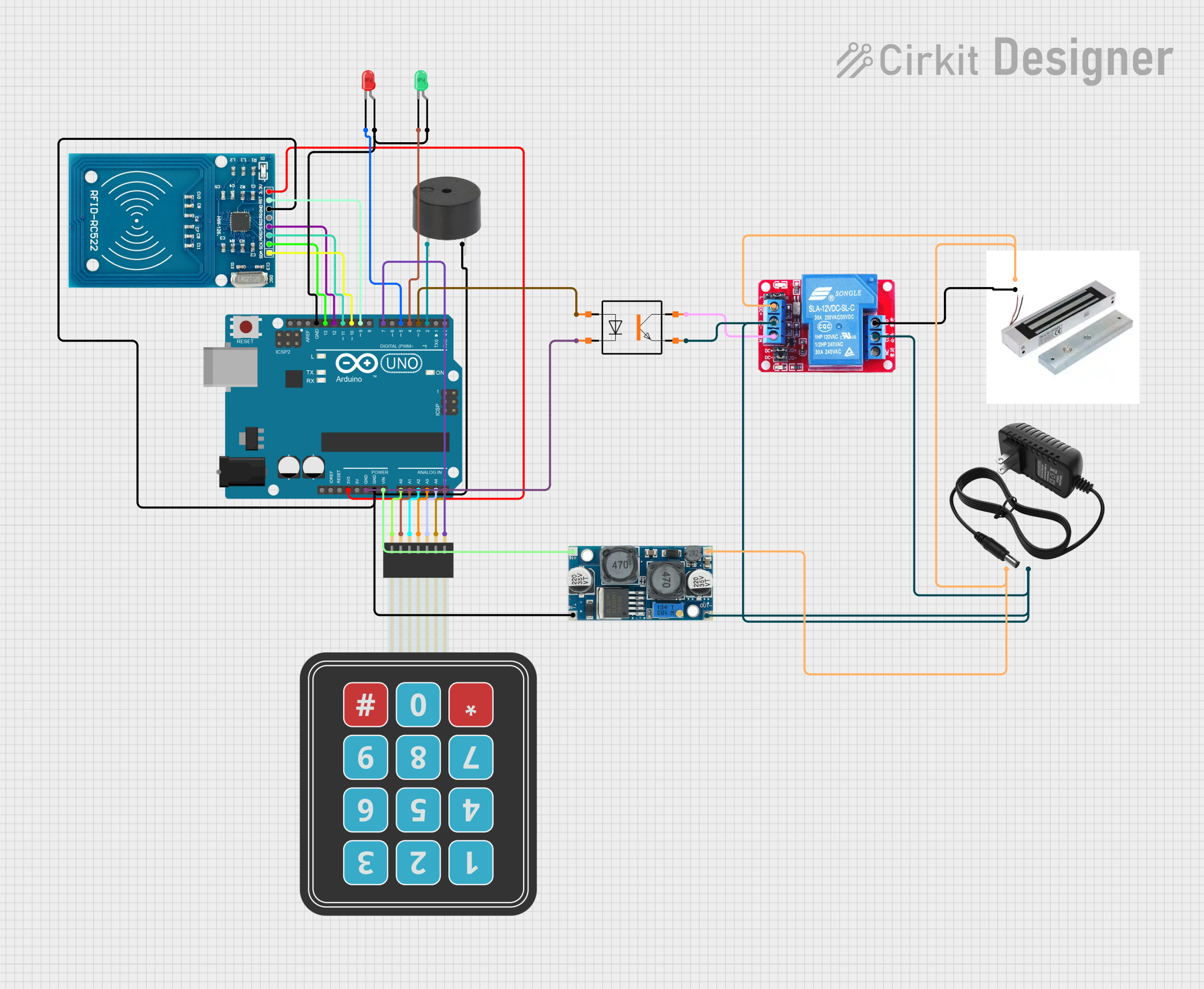
Arduino UNO RFID Door Lock System with Keypad and Buzzer
Circuit Documentation
Summary
This document provides a detailed overview of a door locking system that utilizes an RFID reader, a membrane matrix keypad, and an Arduino UNO microcontroller. The system allows for the registration of new RFID cards, validation of access using a numeric code, and deletion of registered cards in case of loss. The system also includes a buzzer for audio feedback and LEDs for visual indicators.
Component List
Arduino UNO
- Description: A microcontroller board based on the ATmega328P.
- Pins: UNUSED, IOREF, Reset, 3.3V, 5V, GND, Vin, A0, A1, A2, A3, A4, A5, SCL, SDA, AREF, D13, D12, D11, D10, D9, D8, D7, D6, D5, D4, D3, D2, D1, D0, Power
RFID-RC522
- Description: An RFID reader module.
- Pins: VCC (3.3V), RST, GND, IRQ, MISO, MOSI, SCK, SDA
Magnetic Lock
- Description: An electromagnetic lock.
- Pins: S, GND
12V Relay
- Description: A relay module for switching high voltage devices.
- Pins: NO, COM, NC, DC+, DC-, IN
LED: Two Pin (Red)
- Description: A red LED.
- Pins: Cathode, Anode
LED: Two Pin (Green)
- Description: A green LED.
- Pins: Cathode, Anode
Buzzer
- Description: A piezoelectric buzzer.
- Pins: PIN, GND
Membrane Matrix Keypad
- Description: A 4x3 matrix keypad.
- Pins: Row 1, Row 2, Row 3, Row 4, Column 1, Column 2, Column 3
PC817 Optotransistor
- Description: An optocoupler.
- Pins: Anode, Cathode, Collector, Emitter
12V Power Supply
- Description: A 12V DC power supply.
- Pins: +, -
XL6009 Voltage Regulator
- Description: A DC-DC step-up voltage regulator.
- Pins: OUT +, OUT -, IN +, IN -
Wiring Details
Arduino UNO
- 3.3V connected to RFID-RC522 VCC (3.3V)
- GND connected to PC817 Optotransistor Cathode, XL6009 Voltage Regulator IN -, RFID-RC522 GND, Buzzer GND, LED (Green) Anode, LED (Red) Anode
- Vin connected to XL6009 Voltage Regulator IN +
- A0 connected to Membrane Matrix Keypad Column 3
- A1 connected to Membrane Matrix Keypad Column 2
- A2 connected to Membrane Matrix Keypad Column 1
- A3 connected to Membrane Matrix Keypad Row 4
- A4 connected to Membrane Matrix Keypad Row 3
- A5 connected to Membrane Matrix Keypad Row 2
- D13 connected to RFID-RC522 SCK
- D12 connected to RFID-RC522 MISO
- D11 connected to RFID-RC522 MOSI
- D10 connected to RFID-RC522 SDA
- D9 connected to RFID-RC522 RST
- D7 connected to Membrane Matrix Keypad Row 1
- D5 connected to LED (Red) Cathode
- D4 connected to LED (Green) Cathode
- D3 connected to PC817 Optotransistor Anode
- D2 connected to Buzzer PIN
RFID-RC522
- VCC (3.3V) connected to Arduino UNO 3.3V
- GND connected to Arduino UNO GND
- SCK connected to Arduino UNO D13
- MISO connected to Arduino UNO D12
- MOSI connected to Arduino UNO D11
- SDA connected to Arduino UNO D10
- RST connected to Arduino UNO D9
Magnetic Lock
- S connected to XL6009 Voltage Regulator OUT +
- GND connected to 12V Relay NO
12V Relay
- NO connected to Magnetic Lock GND
- COM connected to XL6009 Voltage Regulator OUT -
- DC+ connected to XL6009 Voltage Regulator OUT +
- DC- connected to XL6009 Voltage Regulator OUT -
- IN connected to PC817 Optotransistor Collector
LED: Two Pin (Red)
- Anode connected to Arduino UNO GND
- Cathode connected to Arduino UNO D5
LED: Two Pin (Green)
- Anode connected to Arduino UNO GND
- Cathode connected to Arduino UNO D4
Buzzer
- PIN connected to Arduino UNO D2
- GND connected to Arduino UNO GND
Membrane Matrix Keypad
- Column 3 connected to Arduino UNO A0
- Column 2 connected to Arduino UNO A1
- Column 1 connected to Arduino UNO A2
- Row 4 connected to Arduino UNO A3
- Row 3 connected to Arduino UNO A4
- Row 2 connected to Arduino UNO A5
- Row 1 connected to Arduino UNO D7
PC817 Optotransistor
- Anode connected to Arduino UNO D3
- Cathode connected to Arduino UNO GND
- Collector connected to 12V Relay IN
- Emitter connected to XL6009 Voltage Regulator OUT -
12V Power Supply
- + connected to XL6009 Voltage Regulator OUT +
- - connected to XL6009 Voltage Regulator OUT -
XL6009 Voltage Regulator
- IN + connected to Arduino UNO Vin
- IN - connected to Arduino UNO GND
- OUT + connected to 12V Power Supply +, Magnetic Lock S, 12V Relay DC+
- OUT - connected to 12V Power Supply -, 12V Relay COM, 12V Relay DC-, PC817 Optotransistor Emitter
Documented Code
/*
 * Ce sketch Arduino contrôle un système de verrouillage de porte utilisant RFID
 * et un clavier matriciel. Le système permet d'enregistrer de nouvelles cartes
 * RFID, de valider l'accès avec un code numérique, et de supprimer des cartes
 * enregistrées en cas de perte. Un buzzer émet des sons différents pour les
 * actions de validation et d'enregistrement.
 */

#include <SPI.h>
#include <MFRC522.h>
#include <Keypad.h>

#define RST_PIN 9
#define SS_PIN 10
#define RED_LED_PIN 5
#define GREEN_LED_PIN 4
#define RELAY_PIN 3
#define BUZZER_PIN 2
#define MAX_ATTEMPTS 5
#define ADDITIONAL_ATTEMPTS 3
#define ALARM_DURATION 60000 // 1 minute in milliseconds
#define LOCK_DURATION 3600000 // 1 hour in milliseconds

MFRC522 mfrc522(SS_PIN, RST_PIN);

const byte ROWS = 4; // four rows
const byte COLS = 3; // three columns
char keys[ROWS][COLS] = {
  {'1','2','3'},
  {'4','5','6'},
  {'7','8','9'},
  {'*','0','#'}
};
byte rowPins[ROWS] = {7, A5, A4, A3};
byte colPins[COLS] = {A2, A1, A0};
Keypad keypad = Keypad(makeKeymap(keys), rowPins, colPins, ROWS, COLS);

byte authorizedUIDs[10][4];
int numAuthorizedUIDs = 0;

int failedAttempts = 0;
int additionalFailedAttempts = 0;
bool isLocked = false;
unsigned long lockStartTime = 0;

void setup() {
  Serial.begin(9600);
  SPI.begin();
  mfrc522.PCD_Init();
  pinMode(RED_LED_PIN, OUTPUT);
  pinMode(GREEN_LED_PIN, OUTPUT);
  pinMode(RELAY_PIN, OUTPUT);
  pinMode(BUZZER_PIN, OUTPUT);
  digitalWrite(RE