
Arduino-Controlled Distance Monitoring System with Multi-Color LED Feedback
View and Edit Project In Cirkit Designer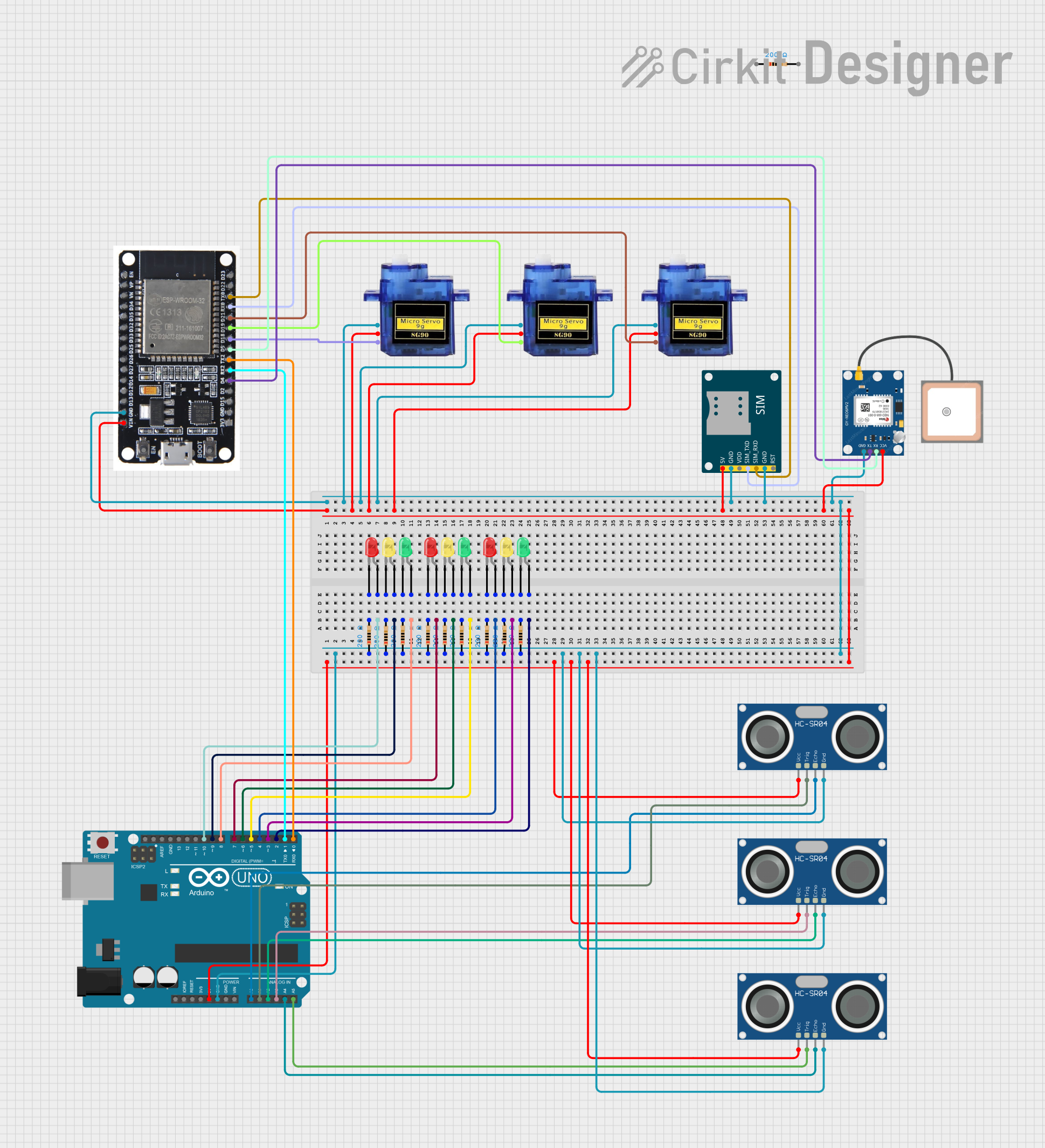
Circuit Documentation
Summary
This circuit is designed to interface with multiple sensors and output devices, including ultrasonic sensors, LEDs, servos, a GSM module, and a GPS module. The primary microcontroller used in this circuit is an Arduino UNO, which controls LEDs based on the distance measurements from the ultrasonic sensors and communicates with an ESP32 microcontroller. The ESP32 handles more complex tasks such as driving servos, interfacing with the GSM module for cellular communication, and receiving GPS data. The circuit is powered by the 5V output from the Arduino UNO, which is distributed to the various components that require power.
Component List
LEDs
- LED (Green): A two-pin green LED used to indicate status or provide visual feedback.
- LED (Yellow): A two-pin yellow LED used similarly to the green LED for different status indications.
- LED (Red): A two-pin red LED used to indicate warnings or critical status.
Resistors
- Resistor (200 Ohms): Used to limit current to the LEDs to prevent damage.
Microcontrollers
- Arduino UNO: The main microcontroller board based on the ATmega328P, used for simple I/O and sensor interfacing.
- ESP32: A powerful microcontroller with Wi-Fi and Bluetooth capabilities, used for more complex tasks and communication.
Sensors
- HC-SR04 Ultrasonic Sensor: Used to measure distance by emitting ultrasonic waves and measuring the time taken for the echo to return.
- GPS NEO 6M: A GPS module used to receive geographic location data.
Communication Modules
- SIM800L GSM Module: A cellular communication module that allows the circuit to send SMS, make calls, and use GPRS for data.
Actuators
- Micro Servo 9G: A small servo motor that can be precisely controlled to move to different positions.
Wiring Details
LEDs
- Green LED: Anode connected to a digital pin on the Arduino UNO, cathode connected to a 200 Ohm resistor, which is then connected to GND.
- Yellow LED: Wired similarly to the green LED, with the anode connected to a different digital pin.
- Red LED: Wired similarly to the green and yellow LEDs, with the anode connected to yet another digital pin.
Resistors
- 200 Ohm Resistor: One end connected to the cathode of an LED, the other end connected to GND.
Microcontrollers
- Arduino UNO: Digital pins used to control LEDs and to interface with ultrasonic sensors. Serial communication pins (RX/TX) used to communicate with the ESP32.
- ESP32: Receives data from the Arduino UNO via serial communication. Controls servo motors and interfaces with the GSM and GPS modules.
Sensors
- HC-SR04 Ultrasonic Sensor: VCC connected to 5V, GND connected to GND, TRIG and ECHO pins connected to designated analog pins on the Arduino UNO.
Communication Modules
- SIM800L GSM Module: 5V and GND connected to power and ground, respectively. SIM_TXD and SIM_RXD connected to the RX0 and TX0 pins on the ESP32 for serial communication.
Actuators
- Micro Servo 9G: GND and +5V connected to power and ground, respectively. PWM pin connected to a designated pin on the ESP32 for control signals.
Documented Code
// Define pins for Ultrasonic Sensor 1
const int trigPin1 = A4;
const int echoPin1 = A5;

// Define pins for Ultrasonic Sensor 2
const int trigPin2 = A2;
const int echoPin2 = A3;

// Define pins for Ultrasonic Sensor 3
const int trigPin3 = A0;
const int echoPin3 = A1;

// Define pins for LEDs (3 for each sensor)
const int greenLED1 = 2;
const int yellowLED1 = 3;
const int redLED1 = 4;

const int greenLED2 = 5;
const int yellowLED2 = 6;
const int redLED2 = 7;

const int greenLED3 = 8;
const int yellowLED3 = 9;
const int redLED3 = 10;

// Variables for sensor timing and distance
long duration1, duration2, duration3;
int distance1, distance2, distance3;

void setup() {
  // Initialize the pins for ultrasonic sensors
  pinMode(trigPin1, OUTPUT);
  pinMode(echoPin1, INPUT);

  pinMode(trigPin2, OUTPUT);
  pinMode(echoPin2, INPUT);

  pinMode(trigPin3, OUTPUT);
  pinMode(echoPin3, INPUT);

  // Initialize the pins for all LEDs
  pinMode(greenLED1, OUTPUT);
  pinMode(yellowLED1, OUTPUT);
  pinMode(redLED1, OUTPUT);

  pinMode(greenLED2, OUTPUT);
  pinMode(yellowLED2, OUTPUT);
  pinMode(redLED2, OUTPUT);

  pinMode(greenLED3, OUTPUT);
  pinMode(yellowLED3, OUTPUT);
  pinMode(redLED3, OUTPUT);

  // Begin serial communication for debugging
  Serial.begin(9600);
}

void loop() {
  // Get distance from Ultrasonic Sensor 1
  distance1 = getDistance(trigPin1, echoPin1);
  Serial.print("Distance 1: ");
  Serial.print(distance1);
  Serial.println(" cm");

  // Set LED states for Sensor 1
  setLEDs(distance1, greenLED1, yellowLED1, redLED1);

  // Get distance from Ultrasonic Sensor 2
  distance2 = getDistance(trigPin2, echoPin2);
  Serial.print("Distance 2: ");
  Serial.print(distance2);
  Serial.println(" cm");

  // Set LED states for Sensor 2
  setLEDs(distance2, greenLED2, yellowLED2, redLED2);

  // Get distance from Ultrasonic Sensor 3
  distance3 = getDistance(trigPin3, echoPin3);
  Serial.print("Distance 3: ");
  Serial.print(distance3);
  Serial.println(" cm");

  // Set LED states for Sensor 3
  setLEDs(distance3, greenLED3, yellowLED3, redLED3);

  // Small delay to avoid bouncing
  delay(500);
}

// Function to calculate distance for each ultrasonic sensor
int getDistance(int trigPin, int echoPin) {
  // Send out the ultrasonic signal
  digitalWrite(trigPin, LOW);
  delayMicroseconds(2);
  digitalWrite(trigPin, HIGH);
  delayMicroseconds(10);
  digitalWrite(trigPin, LOW);

  // Read the echo pin to get the signal's duration
  long duration = pulseIn(echoPin, HIGH);

  // Calculate the distance in centimeters
  int distance = duration * 0.034 / 2;

  return distance;
}

// Function to control LEDs based on distance
void setLEDs(int distance, int greenLED, int yellowLED, int redLED) {
  if (distance > 30) {
    // Green LED for distance greater than 30 cm
    digitalWrite(greenLED, HIGH);
    digitalWrite(yellowLED, LOW);
    digitalWrite(redLED, LOW);
  } else if (distance <= 30 && distance > 10) {
    // Yellow LED for distance between 10 cm and 30 cm
    digitalWrite(greenLED, LOW);
    digitalWrite(yellowLED, HIGH);
    digitalWrite(redLED, LOW);
  } else if (distance <= 10) {
    // Red LED for distance less than 10 cm
    digitalWrite(greenLED, LOW);
    digitalWrite(yellowLED, LOW);
    digitalWrite(redLED, HIGH);
  }
}
This code is designed to run on the Arduino UNO microcontroller. It initializes the pins for the ultrasonic sensors and LEDs, reads distances from the sensors, and sets the LED states based on these distances. The getDistance function sends an ultrasonic pulse and calculates the distance based on the time taken for the echo to return. The setLEDs function controls the state of the LEDs based on the measured distance.